| 6.4. VRML scene class for OpenGL | ||
|---|---|---|
 | Chapter 6. OpenGL rendering |  |
TCastleScene is a descendant of
TCastleSceneCore (which was introduced earlier in
Section 3.10, “VRML scene”). Internally it uses
TGLRenderer (introduced in last section,
Section 6.3, “Basic OpenGL rendering”) to render scene
to OpenGL. It also provides higher-level optimizations and features for
OpenGL rendering. In short, this is the most comfortable
and complete class that you should use to load and render static
VRML models. In addition to TCastleSceneCore features,
it allows you to:
Render all shapes (i.e. whole VRML scene). Use
Rendermethod withnilasTestShapeVisibilityparameter for the simplest rendering method.You can render only the shapes that are within current camera frustum by
RenderFrustum. This works by checking each shape for collision with frustum before rendering. Generally, it makes a great rendering optimization if user doesn't usually see the whole scene at once.When you initialize shape octree for rendering, by adding
ssRenderingtoTCastleScene.Spatial, thenRenderFrustumwill work even better. The shapes within the frustum will be determined by traversing the shape octree. If your scene has many shapes then this will be faster than without octree.In special cases you may be able to create a specialized test whether given shape is visible. You can call
Rendermethod passing as a parameter pointer to your specialized test routine. This way you may be able to add some special optimizations in particular cases.For example if you know that the scene uses a dense fog and it has a matching background color (for example by
BackgroundVRML node) then it's sensible to ignore shapes that are further then fog's visibility range. In other words, you only draw shapes within a sphere around the player position.A working example program that uses exactly this approach is available in our engine sources in the file
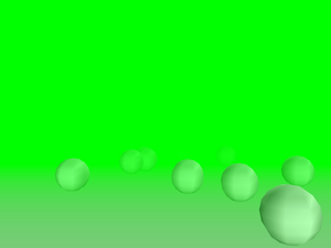
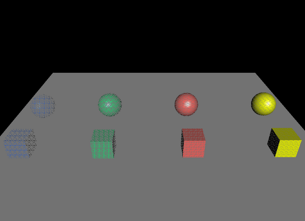
castle_game_engine/examples/vrml/fog_culling.lpr.On the screenshot below the fog is turned off. Camera frustum culling is used to optimize rendering, and so only 297 spheres out of all 866 spheres on the scene need to be rendered.
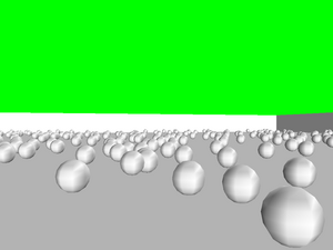
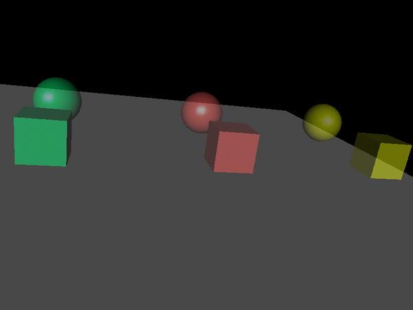
On the next screenshot the fog is turned on. The same view is rendered. We render only the objects within fog visibility range, and easily achieve a drastic improvement: only 65 spheres are passed to OpenGL now. Actually we could improve this result even more: in this case, both camera frustum culling and culling to the fog range could be used. Screenshot suggests that only 9 spheres would be rendered then.
Figure 6.5. Rendering with the fog (only objects within the fog visibility range need to be rendered)
TCastleSceneimplements material transparency by OpenGL alpha blending. This requires rearranging the order in which shapes are rendered, that's why it must be done in this class (instead of being done insideTGLRenderer).Details about this will be revealed soon in Section 6.4.1, “Material transparency using OpenGL alpha blending”.
TCastleScenehas also comfortable methods to handle and render VRMLBackgroundnode of your scene.
To understand the issue you have to understand how OpenGL
works. OpenGL doesn't “remember” all the triangles sent to it.
As soon as you finish passing a triangle to OpenGL (which means
making glVertex call that completes the triangle)
OpenGL implementation is free to immediately render it.
This means mapping the given triangle to 2D window and updating data
in various buffers — most notably the color buffer, but also
the depth buffer, the stencil buffer and possibly others.
Right after triangle is rendered this way, OpenGL implementation
can completely “forget” about the fact that it just
rendered the triangle. All triangle geometry, materials etc.
information doesn't have to be kept anywhere. The only trace
after rendering the triangle is left in the buffers (but these
are large 2D arrays of data, and only the human eye can reconstruct
the geometry of the triangle by looking at the color buffer contents).
In summary, this means that the order in which you pass the triangles to OpenGL is significant. Rendering opaque objects with the help of depth buffer is the particular and simple case when this order doesn't matter (aside for issues related to depth buffer inaccuracy or overlapping geometry). But generally the order matters. Using alpha blending is one such case.
To implement VRML material transparency we use materials with alpha (4th color component) set to value lower than 1.0. When the triangle is specified, OpenGL renders it. A special operation mode is done for updating color buffer: instead of overriding old color values, the new and old colors are mixed, taking into account alpha (which acts as opacity factor here) value. Of course when rendering transparent triangles they still must be tested versus depth buffer, that contains at this point information about all the triangles rendered so far within this frame.
Now observe that depth buffer should not be updated as a result of rendering partially transparent triangle. Reason: partially transparent triangle doesn't hide the geometry behind it. If we will happen to render later other triangle (partially transparent or opaque) behind current partially transparent triangle, then the future triangle should not be eliminated by the current triangle. So only rendering opaque objects can change depth buffer data, and thus opaque objects hide all (partially transparent or opaque) objects behind them.
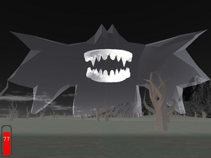
But what will happen now if you render opaque triangle that is behind already rendered partially transparent triangle? The opaque triangle will cover the partially transparent one, because the information about partially transparent triangle was not recorded in depth buffer. For example you will get this incorrect result:
Figure 6.6. The ghost creature on this screenshot is actually very close to the player. But it's transparent and is rendered incorrectly: gets covered by the ground and trees.
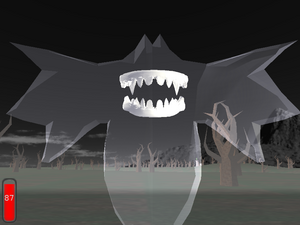
The solution is to avoid this situation and render all partially transparent objects after all opaque objects. This will give correct result, like this:
Figure 6.7. The transparent ghost rendered correctly: you can see that it's floating right before the player.
Actually, in a general situation, rendering all partially
transparent objects after opaque objects is not enough.
That's because if more than one transparent object is visible on the
same screen pixel, then the order in which they are rendered matters —
because they are blended with color buffer in the same order as they
are passed to OpenGL. For example if you set your blending functions
to standard (GL_SRC_ALPHA,
GL_ONE_MINUS_SRC_ALPHA) then each time
you render a triangle with color (Red, Green, Blue) and opacity α,
the current screen pixel color (ScreenRed,
ScreenGreen, ScreenBlue)
changes to
(ScreenRed, ScreenGreen, ScreenBlue) * (1 - α) + (Red, Green, Blue) * α
Consider for example two partially transparent triangles, one of them red and the second one green, both with α set to 0.9. Suppose that they are both visible on the same pixel. If you render the red triangle first, then the pixel color will be
ScreenColor * (1 - α) * (1 - α) +
RedColor * α * (1 - α) + GreenColor * α =
ScreenColor * 0.01 + RedColor * 0.09 + GreenColor * 0.9 =
visible as GreenColor in practice
If you render green triangle first then the analogous calculations will get you pixel color close to the red.
So the more correct solution to this problem is to sort your transparent
triangles with respect to their distance from the viewer.
You should render first the objects that are more distant.
Since April 2009 you can activate sorting shapes of transparent
objects by setting Attributes.BlendingSort := true.
However, this solution isn't really perfect. Sorting shapes is only an approximation, in more general case you should sort single triangles. Sorting all triangles at each frame (or after each camera move) doesn't seem like a good idea for a 3D simulation that must be done in real-time as fast as possible. Moreover, there are pathological cases when even sorting triangles is not enough and you will have to split triangles to get things 100% right. So it's just not possible to overcome the problem without effectively sorting at each screen pixel separately, which is not doable without hardware help.
That's why our engine by default just ignores the order problem
(Attributes.BlendingSort is false
by default). We do not
pay any attention to the order of rendering of transparent
objects — as long as they are rendered after all opaque objects.
In practice, rendering artifacts will occur only in some complex combinations of
transparent objects. If you seldom use a transparent object,
then you have small chance of ever hitting the situation that actually
requires you to sort the triangles. Moreover, even in these situations,
the rendering artifacts are usually not noticeable to casual user. Fast real-time
rendering is far more important that 100% accuracy here.
Moreover, our engine right now by default uses
(GL_SRC_ALPHA, GL_ONE)
blending functions, which means that the resulting pixel color
is calculated as
(ScreenRed, ScreenGreen, ScreenBlue) + (Red, Green, Blue) * α
That is, the current screen color is not scaled by (1 - α).
We only add new color, scaled by it's alpha. This way rendering
order of the transparent triangles doesn't matter — any order will
produce the same results. For some uses
(GL_SRC_ALPHA, GL_ONE)
functions look better than (GL_SRC_ALPHA,
GL_ONE_MINUS_SRC_ALPHA), for some uses they are worse.
(GL_SRC_ALPHA, GL_ONE) tend
to make image too bright (since transparent objects only increase the
color values), that's actually good as long as your transparent objects
represent some bright-colored and dense objects (a thick plastic glass,
for example). (GL_SRC_ALPHA,
GL_ONE_MINUS_SRC_ALPHA) on the other hand can
sometimes unnaturally darken the opaque objects behind (since that's
what these functions will do for a dark transparent object with large alpha).
Other method of rendering material transparency deserves a quick note here. It's done by polygon stipple, which means that transparent triangles are rendered using special bit mask. This way part of their pixels are rendered as opaque, and part of them are not rendered at all. This creates a transparent look on sufficiently large resolution. Order of rendering transparent objects doesn't matter in this case.
However, the practical disadvantages of this method is that it looks quite, well, ugly. When we use random stipples (to precisely show different transparency of different objects) then the random stipples look very ugly:
Instead of using random stipples, we can use a couple of special good-looking prepared regular stipples. But then we don't have much ability to accurately represent various transparency values (especially for very transparent objects). And still the results look quite bad:
Optimizations done by TCastleScene
(in particular, frustum culling) work best when the scene
is sensibly divided into a number of small shapes.
This means that “internal” design of VRML model (how it's
divided into shapes) matters a lot. Here are some guidelines for
VRML authors:
Don't define your entire world model as one
IndexedFaceSetnode, as this makes frustum culling compare frustum only with bounding box of the whole scene. Unless your scene is usually visible completely / not visible at all on the screen, in which case this is actually a good idea.Avoid
IndexedFaceSetnodes with triangles that are scattered all around the whole scene. Such nodes will have very large bounding box and will be judged as visible from almost every camera position in the scene, thus making optimizations like frustum culling less efficient.An ideal VRML model is split into many shapes that have small bounding boxes. It's hard to specify a precise “optimal” number of shapes, so you should just test your VRML model as much as you can. Generally,
RenderFrustumwithssRenderingoctree should be able to handle efficiently even models with a lot of shapes.
Then comes an idea to use scene division into triangles instead of shapes. This would mean that our optimization doesn't depend on shape division so much. Large shapes would no longer be a problematic case.
To make this work we would have to traverse triangle octree to decide which triangles are in the visibility frustum. Doing this without the octree, i.e. testing each triangle against the frustum, would be pointless, since this is what OpenGL already does by itself.
Such traversing of the octree would have to be the first pass, used only to mark visible triangles. In the second pass we would take each shape and render marked triangles from it. The reason for this two-pass approach is that otherwise (if we would try to render triangles immediately when traversing the octree) we would produce too much overhead for OpenGL. Overhead would come from changing material/texture/etc. properties very often, since we would probably find triangles from various nodes (with various properties) very close in some octree leafs.
But this approach creates problems:
The rendering routines would have to be written much more intelligently to avoid rendering unmarked triangles. This is not as easy as it seems as it collides with some smart tricks to improve vertex sharing, like using OpenGL primitives (
GL_QUAD_STRIPetc.).We would be unable to put large parts of rendering pipeline into OpenGL arrays. Constructing separate VBO for each triangle has little sense.
That's why this approach is not implemented.
| |  | |
| 6.3. Basic OpenGL rendering |  | Chapter 7. Animation |