| 1.3. Children nodes | ||
|---|---|---|
 | Chapter 1. Overview of VRML |  |
Now we're approaching the fundamental idea of VRML: some
nodes can be placed as a children of other nodes. We already
saw some examples of this idea in VRML 2.0 examples
above: we placed various nodes inside geometry
field of Shape node. VRML 1.0 has a little different
way of specifying children nodes (inherited from Inventor format)
than VRML 2.0 and X3D — we will see both methods.
In VRML 1.0, you just place children nodes inside the parent node. Like this:
#VRML V1.0 ascii

Group {
  Sphere { }
  Cube { width 1.5 height 1.5 depth 1.5 }
}
Group is the simplest grouping node.
It has no fields, and it's only purpose is just to treat a couple of nodes
as one node.
Note that in VRML 1.0 it's required that a whole VRML file consists of exactly one root node, so we actually had to use some grouping node here. For example the following file is invalid according to VRML 1.0 specification:
#VRML V1.0 ascii

Sphere { }
Cube { width 1.5 height 1.5 depth 1.5 }
Nevertheless the above example is handled by many VRML engines, including our engine described in this document.
In VRML 2.0, you don't place children nodes directly
inside the parent node. Instead you place children nodes inside
fields of type SFNode (this contains
zero (NULL) or one node) or
MFNode (this contains any number (possibly zero)
of nodes). For example, in VRML 2.0 Group
node has an MFNode field children,
so the example file in VRML 2.0 equivalent to previous example looks like
this:
#VRML V2.0 utf8

Group {
  children [
    Shape { geometry Sphere { } }
    Shape { geometry Box { size 1.5 1.5 1.5 } }
  ]
}
Syntax of MFNode is just like for other multiple-valued
fields: a sequence of values, inside brackets ([
and ]).
Example above also shows a couple of other differences between VRML 1.0 and 2.0:
In VRML 2.0 we have to wrap
SphereandBoxnodes inside aShapenode.Node
Cubefrom VRML 1.0 was renamed toBoxin VRML 2.0.Size of the box in VRML 2.0 is specified using
sizefield of typeSFVec3f, while in VRML 1.0 we had three fields (width,height,depth) of typeSFFloat.
While we're talking about VRML versions differences, note also that
in VRML 2.0 a file can have any number of root nodes. So actually
we didn't have to use Group node in our example,
and the following would be correct VRML 2.0 file too:
#VRML V2.0 utf8

Shape { geometry Sphere { } }
Shape { geometry Box { size 1.5 1.5 1.5 } }
To be honest, we have to point one more VRML difference: as was mentioned before, in VRML 2.0 shapes are unlit by default. So our VRML 2.0 examples above look like this:
To make them lit, we must assign a material
for them. In VRML 2.0 you do this by placing a Material
node inside material field of Appearance
node. Then you place Appearance node inside
appearance field of
appropriate Shape node. Result looks like this:
#VRML V2.0 utf8

Group {
  children [
    Shape {
      appearance Appearance { material Material { } }
      geometry Sphere { }
    }
    Shape {
      appearance Appearance { material Material { } }
      geometry Box { size 1.5 1.5 1.5 }
    }
  ]
}
We didn't specify any Material node's fields,
so the default properties will be used. Default VRML 2.0 material properties
are the same as for VRML 1.0: light gray diffuse color and a slight
ambient color.
As you can see, VRML 2.0 description gets significantly more verbose than VRML 1.0, but it has many advantages:
The way how children nodes are specified in VRML 2.0 requires you to always write an
SFNodeorMFNodefield name (as opposed to VRML 1.0 where you just write the children nodes). But the advantages are obvious: in VRML 2.0 you can explicitly assign different meaning to different children nodes by placing them within different fields. In VRML 1.0 all the children nodes had to be treated in the same manner — the only thing that differentiated children nodes was their position within the parent.As mentioned earlier, the default behavior of various VRML 2.0 parts is the one that is the easiest to render. That's why the default behavior is to render unlit, and you have to explicitly specify material to get lit objects.
This is a good thing, since it makes VRML authors more conscious about using features, and hopefully it will force them to create VRML worlds that are easier to render. In the case of rendering unlit objects, this is often perfectly acceptable (or even desired) solution if the object has a detailed texture applied.
Placing the
Materialnode inside theSFNodefield ofAppearance, and then placing theAppearancenode inside theSFNodefield ofShapemay seem like a “bondage-and-discipline language”, but it allows various future enhancements of the language without breaking compatibility. For example you could invent a node that allows to specify materials using a different properties (like by describing it's BRDF function, useful for rendering realistic images) and then just allow this node as a value for thematerialfield.Scenario described above actually happened. First versions of VRML 97 specification didn't include geospatial coordinates support, including a node
GeoCoordinate. A nodeIndexedFaceSethas a fieldcoordused to specify a set of points for geometry, and initially you could place aCoordinatenode there. When specification of geospatial coordinates support was formulated (and added to VRML 97 specification as optional for VRML browsers), all that had to be changed was to say that now you can placeGeoCoordinateeverywhere where earlier you could use onlyCoordinate.The
Shapenode in VRML 2.0 contains almost whole information needed to render given shape. This means that it's easier to create a VRML rendering engine. We will contrast this with VRML 1.0 approach that requires a lot of state information in Section 1.5, “VRML 1.0 state”.
Let's take a look at another grouping node:
VRML 2.0 Transform
node. This node specifies a transformation (a mix
of a translation, a rotation and a scale) for all it's children nodes.
The default field values are such that no transformation actually
takes place, because by default we translate by (0, 0, 0) vector,
rotate by zero angle and scale by 1.0 factor. This means that
the Transform node with all fields left as default
is actually equivalent to a Group node.
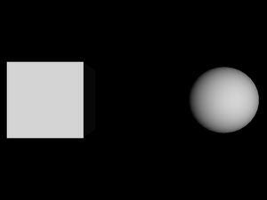
Example of a simple translation:
#VRML V2.0 utf8

Shape {
  appearance Appearance { material Material { } }
  geometry Box { }
}

Transform {
  translation 5 0 0
  children Shape {
    appearance Appearance { material Material { } }
    geometry Sphere { }
  }
}
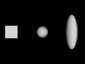
Note that a child of a Transform node
may be another Transform node. All transformations
are accumulated. For example these two files are equivalent:
#VRML V2.0 utf8

Shape {
  appearance Appearance { material Material { } }
  geometry Box { }
}

Transform {
  translation 5 0 0
  children [
    Shape {
      appearance Appearance { material Material { } }
      geometry Sphere { }
    }

    Transform {
      translation 5 0 0
      scale 1 3 1
      children Shape {
        appearance Appearance { material Material { } }
        geometry Sphere { }
      }
    }
  ]
}
#VRML V2.0 utf8
Shape {
appearance Appearance { material Material { } }
geometry Box { }
}
Transform {
translation 5 0 0
children Shape {
appearance Appearance { material Material { } }
geometry Sphere { }
}
}
Transform {
translation 10 0 0
scale 1 3 1
children Shape {
appearance Appearance { material Material { } }
geometry Sphere { }
}
}
A
Switchnode allows you to choose only one (or none) from children nodes to be in the active (i.e. visible, participating in collision detection etc.) part of the scene. This is useful for various scripts and it's also useful for hiding nodes referenced later — we will see an example of this in Section 1.4, “DEF / USE mechanism”.A
Separatorand aTransformSeparatornodes in VRML 1.0. We will see what they do in Section 1.5, “VRML 1.0 state”.A
LODnode (the name is an acronym for level of detail) specifies a different versions of the same object. The intention is that all children nodes represent the same object, but with different level of detail: first node is the most detailed one (and difficult to render, check for collisions etc.), second one is less detailed, and so on, until the last node has the least details (it can even be empty, which can be expressed by aGroupnode with no children). VRML browser should choose the appropriate children to render based on the distance between the viewer and designated center point.A
Collisionnode is available in VRML 2.0 and X3D. It's very useful to disable collisions for particular shapes (visible but not collidable geometry), or to specify a “proxy” shape to be used for collisions. “Proxy” can be used to perform collisions with a complicated 3D object by a simpler shape, for example a complicated statue of a human could be surrounded by a simple box proxy for the sake of collisions. Also, this can be used to make collidable but invisible geometry.
| |  | |
| 1.2. Fields |  | 1.4. DEF / USE mechanism |