| 1.5. VRML 1.0 state | ||
|---|---|---|
 | Chapter 1. Overview of VRML |  |
In previous sections most of the examples were given only in VRML 2.0 version. Partially that's because VRML 2.0 is just newer and better, so you should use it instead of VRML 1.0 whenever possible. But partially that was because we avoided to explain one important behavior of VRML 1.0. In this section we'll fill the gap. Even if you're not interested in VRML 1.0 anymore, this information may help you understand why VRML 2.0 was designed the way it was, and why it's actually better than VRML 1.0. That's because part of the reasons of VRML 2.0 changes were to avoid the whole issue described here.
Historically, VRML 1.0 was based on Inventor file format,
and Inventor file format was
designed specifically with OpenGL implementation in mind.
Those of you who do any programming in OpenGL know that OpenGL
works as a state machine. This means
that OpenGL remembers a lot of “global” settings
[5]. When you want to render
a vertex (aka point) in OpenGL, you just call one simple command
(glVertex), passing only point coordinates.
And the vertex is rendered (along with a line or even a triangle
that it produces with other vertexes). What color does the vertex
has? The last color specified by glColor
call (or glMaterial, mixed with lights).
What texture coordinate does it have? Last texture coordinate
specified in glTexCoord call. What texture
does it use? Last texture bound with glBindTexture.
We can see a pattern here: when you want to know what property
our vertex has, you just have to check what value we last assigned
to this property. When we talk about OpenGL state, we talk
about all the “last glColor”,
“last glTexCoord” etc. values
that OpenGL has to remember.
Inventor, and then VRML 1.0, followed a similar approach.
“What material does a sphere use?” The one specified in the last
Material node. Take a look at the example:
#VRML V1.0 ascii

Group {
  # Default material will be used here:
  Sphere { }

  DEF RedMaterial Material { diffuseColor 1 0 0 }

  Transform { translation 5 0 0 }
  # This uses the last material : red
  Sphere { }

  Transform { translation 5 0 0 }
  # This still uses uses the red material
  Sphere { }

  Material { diffuseColor 0 0 1 }

  Transform { translation 5 0 0 }
  # Material changed to blue
  Sphere { }

  Transform { translation 5 0 0 }
  # Still blue...
  Sphere { }

  USE RedMaterial

  Transform { translation 5 0 0 }
  # Red again !
  Sphere { }

  Transform { translation 5 0 0 }
  # Still red.
  Sphere { }
}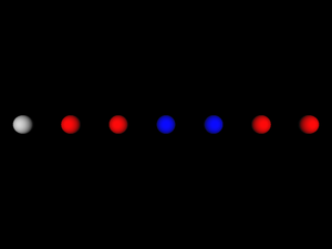
Similar answers are given for other questions in the form “What is used?”. Let's compare VRML 1.0 and 2.0 answers for such questions:
What texture is used?
VRML 1.0 answer: Last
Texture2node.VRML 2.0 answer: Node specified in enclosing
Shapeappearance'stexturefield.What coordinates are used by
IndexedFaceSet?VRML 1.0 answer: Last
Coordinate3node.VRML 2.0 answer: Node specified in
coordfield of givenIndexedFaceSet.What font is used by by
AsciiTextnode (renamed to justTextin VRML 2.0)?VRML 1.0 answer: Last
FontStylenode.VRML 2.0 answer: Node specified in
fontStylefield of givenTextnode.
So VRML 1.0 approach maps easily to OpenGL.
Simple VRML implementation can just traverse the scene graph,
and for each node do appropriate set of OpenGL calls.
For example, Material node will correspond
to a couple of glMaterial and glColor
calls. Texture2 will correspond to binding
prepared OpenGL texture. Visible geometry nodes will cause
rendering of appropriate geometry, and so last
Material and Texture2
settings will be used.
In our example with materials above you can also
see another difference between VRML 1.0 and 2.0,
also influenced by the way things are done in OpenGL:
the way Transform node is used.
In VRML 2.0, Transform affected it's children.
In VRML 1.0, Transform node is not supposed to
have any children. Instead, it affects all subsequent nodes.
If we would like to translate last example to VRML 2.0,
each Transform node would have to be placed
as a last child of previous Transform node,
thus creating a deep nodes hierarchy. Alternatively, we could
keep the hierarchy shallow and just use
Transform { translation 5 0 0 ... }
for the first time, then Transform { translation 10 0 0 ... },
then Transform { translation 15 0 0 ... } and so on.
This means that simple VRML 1.0 implementation will just call
appropriate matrix transformations when processing Transform
node. In VRML 1.0 there are even more specialized
transformation nodes. For example a node Translation
that has a subset of features of full Transform node:
it can only translate. Such Translation
has an excellent, trivial mapping to OpenGL: just call
glTranslate.
There's one more important feature of OpenGL
“state machine” approach: stacks. OpenGL has a matrix
stack (actually, three matrix stacks for each matrix type) and
an attributes stack. As you can guess, there are nodes in VRML 1.0
that, when implemented in an easy way, map perfectly
to OpenGL push/pop stack operations: Separator
and TransformSeparator. When you use
Group node in VRML 1.0, the properties
(like last used Material and Texture2,
and also current transformation and texture transformation)
“leak” outside of Group node,
to all subsequent nodes.
But when you use Separator,
they do not leak out: all transformations and “who's the last
material/texture node” properties are unchanged
after we leave Separator node.
So simple Separator implementation in OpenGL
is trivial:
At the beginning, use
glPushAttrib(saving all OpenGL attributes that can be changed by VRML nodes) andglPushMatrix(for both modelview and texture matrices).Then process all children nodes of
Separator.Then restore state by
glPopAttribandglPopMatrixcalls.
TransformSeparator is a cross between
a Separator and a Group:
it saves only transformation matrix, and the rest of the state
can “leak out”. So to implement this in OpenGL,
you just call glPushMatrix (on modelview matrix)
before processing children and glPopMatrix
after.
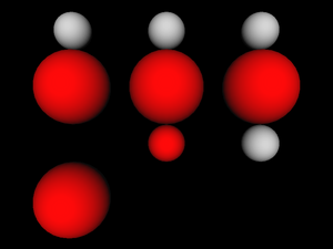
Below is an example how various VRML 1.0 grouping nodes allow
“leaking”. Each column starts with a standard
Sphere node. Then we enter some
grouping node (from the left: Group,
TransformSeparator and Separator).
Inside the grouping node we change material, apply scaling transformation
and put another Sphere node — middle
row always contains a red large sphere. Then we exit
from grouping node and put the third Sphere node.
How does this sphere look like depends on used grouping node.
#VRML V1.0 ascii

Separator {
  Sphere { }
  Transform { translation 0 -3 0 }
  Group {
    Material { diffuseColor 1 0 0 }
    Transform { scaleFactor 2 2 2 }
    Sphere { }
  }
  # A Group, so both Material change and scaling "leaks out"
  Transform { translation 0 -3 0 }
  Sphere { }
}

Transform { translation 5 0 0 }

Separator {
  Sphere { }
  Transform { translation 0 -3 0 }
  TransformSeparator {
    Material { diffuseColor 1 0 0 }
    Transform { scaleFactor 2 2 2 }
    Sphere { }
  }
  # A TransformSeparator, so only Material change "leaks out"
  Transform { translation 0 -3 0 }
  Sphere { }
}

Transform { translation 5 0 0 }

Separator {
  Sphere { }
  Transform { translation 0 -3 0 }
  Separator {
    Material { diffuseColor 1 0 0 }
    Transform { scaleFactor 2 2 2 }
    Sphere { }
  }
  # A Separator, so nothing "leaks out".
  # The last sphere is identical to the first one.
  Transform { translation 0 -3 0 }
  Sphere { }
}
There are some advantages of VRML 1.0 “state” approach:
It maps easily to OpenGL.
Such easy mapping may be also quite efficient. For example, if two nodes use the same
Materialnode, we can just change OpenGL material once (at the timeMaterialnode is processed). VRML 2.0 implementation must remember last setMaterialnode to achieve this purpose.It's flexible. The way transformations are specified in VRML 2.0 forces us often to create deeper node hierarchies than in VRML 1.0.
And in VRML 1.0 we can easier share materials, textures, font styles and other properties among a couple of nodes. In VRML 2.0 such reusing requires naming nodes by DEF / USE mechanism. In VRML 1.0 we can simply let a couple of nodes have the same node as their last
Material(or similar) node.
But there are also serious problems with VRML 1.0 approach, that VRML 2.0 solves.
The argumentation about “flexibility” of VRML 1.0 above looks similar to argumentation about various programming languages (...programming languages that should remain nameless here...), that are indeed flexible but also allow the programmer to “shoot himself in the foot”. It's easy to forget that you changed some material or texture, and accidentally affect more than you wanted.
Compare this with the luxury of VRML 2.0 author: whenever you start writing a
Shapenode, you always start with a clean state: if you don't specify a texture, shape will not be textured, if you don't specify a material, shape will be unlit, and so on. If you want to know how givenIndexedFaceSetwill look like when rendered, you just have to know it's enclosingShapenode. More precisely, the only things that you have to know for VRML 2.0 node to render it areenclosing
Shapenode,accumulated transformation from
Transformnodes,and some “global” properties: lights that affect this shape and fog properties. I call them “global” because usually they are applied to the whole scene or at least large part of it.
On the other hand, VRML 1.0 author or reader (human or program) must carefully analyze the code before given node, looking for last
Materialnode occurrence etc.The argumentation about “simple VRML 1.0 implementation” misses the point that such simple implementation will in fact suffer from a couple of problems. And fixing these problems will in fact force this implementation to switch to non-trivial methods. The problems include:
OpenGL stacks sizes are limited, so a simple implementation will limit allowed depth of
SeparatorandTransformSeparatornodes.If we will change OpenGL state each time we process a state-changing node, then we can waste a lot of time and resources if actually there are no shapes using given property. For example this code
Separator {
  Texture2 { filename "texture.png" }
}
will trick a naive implementation into loading from file and then loading to OpenGL context a completely useless texture data.
This seems like an irrelevant problem, but it will become a large problem as soon as we will try to use any technique that will have to render only parts of the scene. For example, implementing material transparency using OpenGL blending requires that first all non-transparent shapes are rendered. Also implementing culling of objects to a camera frustum will make many shapes in the scene ignored in some frames.
Last but not least: in VRML 1.0, grouping nodes must process their children in order, to collect appropriate state information needed to render each geometry. In VRML 2.0, there is no such requirement. For example, to render a
Groupnode in VRML 2.0, implementation can process and render children nodes in any order. Like said above, VRML 2.0 must only know about current transformation and global things like fog and lights. The rest of information needed is always contained within appropriateShapenode.VRML 2.0 implementation can even ignore some children in
Groupnode if it's known that they are not visible.Example situations when implementation should be able to freely choose which shapes (and in what order) are rendered were given above: implementing transparency using blending, and culling to camera frustum.
More about the way how we solved this problem for both VRML 1.0 and 2.0 in Section 3.10, “VRML scene”. More about OpenGL blending and culling to frustum in Section 6.4, “VRML scene class for OpenGL”.
[5] Actually, they are remembered for each OpenGL context. And, ideally, they are partially “remembered” on graphic board. But we limit our thinking here only to the point of view of a typical program using OpenGL.
| |  | |
| 1.4. DEF / USE mechanism |  | 1.6. Other important VRML features |