| 1.6. Other important VRML features | ||
|---|---|---|
 | Chapter 1. Overview of VRML |  |
Now that we're accustomed with VRML syntax and concepts, let's take a quick look at some notable VRML features that weren't shown yet.
A powerful tool of VRML is the ability to include one
model as a part of another. In VRML 2.0 we do this by
Inline node. It's url
field specifies the URL (possibly relative) of VRML file to load.
Note that our engine doesn't actually support URLs right now
and treats this just as a file name.
The content of referenced VRML file is placed at the position
of given Inline node. This means that you
can apply transformation to inlined content. This also
means that including the same file more than once is sensible
in some situations. But remember the remarks in Section 1.4, “DEF / USE mechanism”:
if you want to include the same file more than once, you should
name the Inline node and then just reuse it.
Such reuse will conserve resources.
url field is actually MFString
and is a sequence of URL values, from the most to least preferred one.
So VRML browser will try to load files from given URLs in order,
until a valid file will be found.
In VRML 1.0 the node is called WWWInline,
and the URL (only one is allowed, it's SFString
field) is specified in the field name.
When using our engine you can mix VRML/X3D versions and include VRML 1.0 file from VRML 2.0, or X3D, or the other way around. Moreover, you can include other 3D formats (like 3DS and Wavefront OBJ) too.
#VRML V2.0 utf8
DEF MyInline Inline { url "reuse_cone.wrl" }
Transform {
translation 1 0 0
rotation 1 0 0 -0.2
children [
USE MyInline
Transform {
translation 1 0 0
rotation 1 0 0 -0.2
children [
USE MyInline
Transform {
translation 1 0 0
rotation 1 0 0 -0.2
children [
USE MyInline
Transform {
translation 1 0 0
rotation 1 0 0 -0.2
children [
USE MyInline
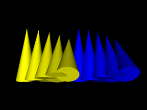
] } ] } ] } ] }Figure 1.15. Our earlier example of reusing cone inlined a couple of times, each time with a slight translation and rotation
VRML allows you to specify a texture coordinate transformation. This allows you to translate, scale and rotate visible texture on given shape.
In VRML 1.0, you do this by Texture2Transform
node — this works analogous to Transform,
but transformations are only 2D. Texture transformations in VRML 1.0
accumulate, just like normal transformations. Here's an example:
#VRML V1.0 ascii

Group {
  Texture2 { filename "../textures/test_texture.png" }

  Cube { }

  Transform { translation 3 0 0 }

  Separator {
    # translate texture
    Texture2Transform { translation 0.5 0.5 }
    Cube { }
  }

  Transform { translation 3 0 0 }

  Separator {
    # rotate texture by Pi/4
    Texture2Transform { rotation 0.7853981634 }
    Cube { }
  }

  Transform { translation 3 0 0 }

  Separator {
    # scale texture
    Texture2Transform { scaleFactor 2 2 }
    Cube { }

    Transform { translation 3 0 0 }

    # rotate texture by Pi/4.
    # Texture transformation accumulates, so this will
    # be both scaled and rotated.
    Texture2Transform { rotation 0.7853981634 }
    Cube { }
  }
}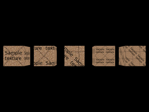
Remember that we transform texture coordinates, so e.g. scale 2x means that the texture appears 2 times smaller.
VRML 2.0 proposes a different approach here:
We have similar TextureTransform node, but we can
use it only as a value for textureTransform field
of Appearance. This also means that there
is no way how texture transformations could accumulate.
Here's a VRML 2.0 file equivalent to previous VRML 1.0 example:
#VRML V2.0 utf8

Shape {
  appearance Appearance {
    texture DEF SampleTexture
      ImageTexture { url "../textures/test_texture.png" }
  }
  geometry Box { }
}

Transform {
  translation 3 0 0
  children Shape {
    appearance Appearance {
      texture USE SampleTexture
      # translate texture
      textureTransform TextureTransform { translation 0.5 0.5 }
    }
    geometry Box { }
  }
}

Transform {
  translation 6 0 0
  children Shape {
    appearance Appearance {
      texture USE SampleTexture
      # rotate texture by Pi/4
      textureTransform TextureTransform { rotation 0.7853981634 }
    }
    geometry Box { }
  }
}

Transform {
  translation 9 0 0
  children Shape {
    appearance Appearance {
      texture USE SampleTexture
      # scale texture
      textureTransform TextureTransform { scale 2 2 }
    }
    geometry Box { }
  }
}

Transform {
  translation 12 0 0
  children Shape {
    appearance Appearance {
      texture USE SampleTexture
      # scale and rotate the texture.
      # There's no way to accumulate texture transformations,
      # so we just do both rotation and scaling by
      # TextureTransform node below.
      textureTransform TextureTransform {
        rotation 0.7853981634
        scale 2 2
      }
    }
    geometry Box { }
  }
}
You can specify various navigation information using
the NavigationInfo node.
typefield describes preferred navigation type. You can “EXAMINE” model, “WALK” in the model (with collision detection and gravity) and “FLY” (collision detection, but no gravity).avatarSizefield sets viewer (avatar) sizes. These typically have to be adjusted for each world to “feel right”. Although you should note that VRML generally suggests to treat length 1.0 in your world as “1 meter”. If you will design your VRML world following this assumption, then defaultavatarSizewill feel quite adequate, assuming that you want the viewer to have human size in your world. Viewer sizes are used for collision detection.Viewer size together with
visibilityLimitmay be also used to set VRML browsers Z-buffer near and far clipping planes. This is the case with our engine. By default our engine tries to calculate sensible values for near and far based on scene bounding box size.You can also specify moving speed (
speedfield), and whether head light is on (headlightfield).
To specify default viewer position and orientation in the
world you use Viewpoint node. In VRML 1.0,
instead of Viewpoint you have
PerspectiveCamera and
OrthogonalCamera (in VRML 2.0 viewpoint
is always perspective). Viewpoint and camera nodes may be generally
specified anywhere in the file. The first viewpoint/camera node
found in the file (but only in the active part of the file —
e.g. not in inactive children of Switch)
will be used as the starting position/orientation.
Note that viewpoint/camera nodes
are also affected by transformation.
Finally, note that my VRML viewer view3dscene has a useful function to print VRML viewpoint/camera nodes ready to be pasted to VRML file, see menu item “Console” -> “Print current camera node”.
Here's an example file. It defines a viewpoint (generated
by view3dscene) and a navigation info
and then includes actual world geometry from other file
(shown in our earlier example
about inlining).
#VRML V2.0 utf8

Viewpoint  {
  position 11.832 2.897 6.162
  orientation -0.463 0.868 0.172 0.810
}

NavigationInfo {
  avatarSize [ 0.5, 2 ]
  speed 1.0
  headlight TRUE
}

Inline { url "inline.wrl" }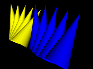
IndexedFaceSet nodes (and a couple of other
nodes in VRML 2.0 like ElevationGrid) have
some notable features to make their rendering better and
more efficient:
You can use non-convex faces if you set
convexfield toFALSE. It will be VRML browser's responsibility to correctly triangulate them. By default faces are assumed to be convex (following the general rule that the default behavior is the easiest one to handle by VRML browsers).By default shapes are assumed to be
solidwhich allows to use backface culling when rendering them.If you don't supply pre-generated normal vectors for your shapes, they will be calculated by the VRML browser. You can control how they will be calculated by the
creaseAnglefield: if the angle between adjacent faces will be less than specifiedcreaseAngle, the normal vectors in appropriate points will be smooth. This allows you to specify preferred “smoothness” of the shape. In VRML 2.0 by defaultcreaseAngleis zero (so all normals are flat; again this follows the rule that the default behavior is the easiest one for VRML browsers). See example below.For VRML 1.0 the
creaseAngle, backface culling and convex faces settings are controlled byShapeHintsnode.All VRML shapes have some sensible default texture mapping. This means that you don't have to specify texture coordinates if you want the texture mapped. You only have to specify some texture. For
IndexedFaceSetthe default texture mapping adjusts to shape's bounding box (see VRML specification for details).
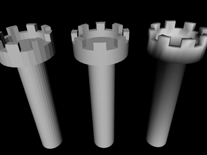
Here's an example of the creaseAngle
use. Three times we define the same geometry in IndexedFaceSet
node, each time using different creaseAngle values.
The left tower uses creaseAngle 0, so all
faces are rendered flat. Second tower uses creaseAngle 1
and it looks good — smooth where it should be.
The third tower uses creaseAngle 4,
which just means that normals are smoothed everywhere (this case
is actually optimized inside our engine, so it's calculated
faster) — it looks bad, we can see that normals are
smoothed where they shouldn't be.
#VRML V2.0 utf8

Viewpoint  {
  position 31.893 -69.771 89.662
  orientation 0.999 0.022 -0.012 0.974
}

Transform {
  children Shape {
    appearance Appearance { material Material { } }
    geometry IndexedFaceSet {
      coord DEF TowerCoordinates Coordinate {
        point [
          4.157832 4.157833 -1.000000,
          4.889094 3.266788 -1.000000,
          ......
        ]
      }

      coordIndex [
        63 0 31 32 -1,
        31 30 33 32 -1,
        ......
      ]
      creaseAngle 0
    }
  }
}

Transform {
  translation 30 0 0
  children Shape {
    appearance Appearance { material Material { } }
    geometry IndexedFaceSet {
      coordIndex [
        63 0 31 32 -1,
        31 30 33 32 -1,
        ......
      ]
      coord USE TowerCoordinates
      creaseAngle 1
    }
  }
}

Transform {
  translation 60 0 0
  children Shape {
    appearance Appearance { material Material { } }
    geometry IndexedFaceSet {
      coordIndex [
        63 0 31 32 -1,
        31 30 33 32 -1,
        ......
      ]
      coord USE TowerCoordinates
      creaseAngle 4
    }
  }
}
- Prototypes
These constructions define new VRML nodes in terms of already available ones. The idea is basically like macros, but it works on VRML nodes level (not on textual level, even not on VRML tokens level) so it's really safe.
- External prototypes
These constructions define syntax of new VRML nodes, without defining their implementation. The implementation can be specified in other VRML file (using normal prototypes mentioned above) or can be deduced by particular VRML browser using some browser-specific means (for example, a browser may just have some non-standard nodes built-in). If a browser doesn't know how to handle given node, it can at least correctly parse the node (and ignore it).
For example, many VRML browsers handle some non-standard VRML nodes. If you use these nodes and you want to make your VRML files at least readable by other VRML browsers, you should declare these non-standard nodes using external prototypes.
Even better, you can provide a list of proposed implementations for each external prototype. They are checked in order, VRML browser should chose the first implementation that it can use. So you can make the 1st item a URN that is recognized only by your VRML browser, and indicating built-in node implementation. And the 2nd item may point to a URL with another VRML file that at least partially emulates the functionality of this non-standard node, by using normal prototype. This way other VRML browsers will be able to at least partially make use of your node.
Our engine handles prototypes and external prototypes perfectly
(since around September 2007). We have some VRML/X3D extensions
(see
Castle Game Engine extensions list),
and they can be declared as external prototypes
with URN like
"urn:castle-engine.sourceforge.net:node:KambiOctreeProperties".
So other VRML browsers should be able to at least parse them.
X3D is a direct successor to VRML 2.0. X3D header even openly
specifies #X3D V3.0 utf8 (or 3.1,
or 3.2) admitting that it's just a 3rd version
of VRML.
X3D is almost absolutely compatible with VRML 2.0, meaning
that almost all VRML 2.0 files are also correct X3D files —
assuming that we change the header to indicate X3D and add trivial
PROFILE line.
Minor incompatible changes include renaming of access specifiers
(exposedField becomes inputOutput,
eventIn becomes inputOnly etc.),
and changes to some field names (Switch.choice and
LOD.level were renamed to Switch.children
and LOD.children, this made the “containerField” mechanism
of X3D XML encoding more useful). There was no revolutionary compatibility
break on the road to X3D, and everything that we said in this chapter
about VRML 2.0 applied also to X3D.
Some of the improvements of X3D:
- Encodings
VRML classic encoding is for compatibility with VRML 2.0.
XML encoding allows to validate and process X3D files with XML tools (like XML Schema, XSLT). It also allows easier implementation, since most programming languages include XML reading/writing support (usually using the DOM API). So you don't have to write lexer and parser (like for classic VRML).
Finally, binary encoding (not implemented in our engine yet) allows smaller files and makes parsing faster.
There is no requirement to support all three encodings in every X3D browser — you only have to support one. XML encoding is the most popular and probably the simpler to implement, so this is the suggested choice. All encodings are completely interchangeable, which means that we can convert X3D files back and forth from any encoding to any other, and no information is lost. Many tools exist to convert from one encoding to the other (our own engine can be used to convert between XML and classic encoding, see https://castle-engine.io/view3dscene.php#section_converting).
- Components and profiles
VRML 2.0 standard was already quite large, and implementing full VRML 2.0 browser was a difficult and long task. At the same time, pretty much everyone who used VRML for more advanced tasks wanted to extend it in some way. So it seemed that the standard was large, and it had to grow even larger... clearly, there was a problem.
The first part of the solution in X3D is to break the standard into many small components. Component is just a part of the specification dealing with particular functionality. The crucial part of each component are it's nodes, and some specification how these nodes cooperate with the rest of the scene. For example, there is a component with 2D geometry, called
Geometry2D. There is a component providing high-level shaders (GLSL, HLSL, Cg) support calledShaders. Currently (as of X3D edition 2) there are 34 components defined by the specification. Every node is part of some component. Naturally, some components depend on other components.Some components are complicated enough to be divided even more — into levels. For example, implementing component on lower level may mean that some node is only optionally supported, or maybe some of it's fields may be ignored, or maybe there may exist some limits on the data. For example, for the
Networkingcomponent, level 1 means that program must support only local (file://) absolute URLs. For level 2, additionallyhttp://must be supported, and URLs may be relative. On level 4 securehttps://must be additionally supported.The author of X3D file can request, at the beginning of X3D file, which components and on what levels must be supported to handle this file. For example, in classic VRML encoding lines
COMPONENT Networking:2
COMPONENT NURBS:1
mean that networking component must be support relative and and absolute
http://andfile://URLs and basic NURBS support is required.Now, the components and levels only divide the standard into small parts. It would be a nightmare to specify at the beginning of each file all required components. It would also do no good to compatibility across X3D browsers: if every browser would be allowed to support any set of any components, we would have no guarantee that even the most basic X3D file is supported by reasonable X3D browsers. So the second part of the solution are profiles. Profile is basically a set of components and their levels, and some additional conditions. There are only few profiles (six, as of X3D edition 2), like
Core,Interchange,InteractiveandFull. The idea is that when browser claims “I support Interchange profile”, then we already know quite a lot about what it supports (Interchange includes most of the static 3D data), and what it possibly doesn't support (interaction, like non-trivial sensors, is not included in the Interchange profile).Each X3D file must state at the beginning which profile it requires to operate. For example, in classic VRML encoding, the
PROFILEline is required, likePROFILE Interchange
Summing it up, the X3D author specifies first the profile and then optionally any number of components (and their levels) which must be supported (in addition to features already requested by the profile). Effectively, X3D browsers can support any components at any level, but they are also strongly pushed to support some high profile. X3D authors can request any profile and components combination they want, and are relatively safe to expect support from most browsers for Interchange or even Interactive profiles.
- New graphic features
As said, there are 34 X3D components, surely there are many new interesting nodes, far too many to actually list them here. You can take a quick look at the X3D specification table of contents at this point.
OK, some of the more interesting additions (not present in VRML 97 amendment 1), in my opinion: humanoid animation (H-Anim), programmable shaders, 3D texturing, cube map environmental texturing, rigid body physics, particle systems.
X3D is supported in our engine since May 2008.
One of the goals of VRML 97 was to allow creating animated and interactive 3D worlds. This feature really sets VRML above other 3D formats. We can define basic animations and interactions in pure VRML language, while also easy and natural integration with scripting languages is possible.
A couple of things make this working:
- Events
Each node has a set of events defined by the VRML standard[6]. There are input events, that can be send to the node (by routes and scripts, we will get to them soon). Input event provides some value to the node and tells the node to do something. There are also output events, that are conceptually generated “by the node”, when some situation occurs. Every event has a type, just like a VRML field. This type says what values can this event receive (input event) or send (output event). Specification says what events are available, and what do they actually do.
For example,
Viewpointnode has an inputset_bindevent ofSFBooltype. When you send aTRUEto this event, then the viewpoint becomes the current viewpoint, making camera jump to it. Thus, you can place manyViewpoints in VRML file, and switch user between them.As an example of output event, there is a
TimeSensornode that continuously sendstimeoutput event (ofSFTimetype). It sends current time value, in seconds (SFTimesimply contains double-precision floating point value).- Exposed fields
The most natural use for events is to set a field's value (by input event), and to generate notification when field's value changed (by output event). For example, we have an input event
set_translationforTransformnode, and analogoustranslation_changedevent. Together withtranslationfield, such triple is called an exposed field.A lot of fields are marked “exposed” in VRML standard. Analogous to above
Transform.translationexample, exposed fieldxxxis a normal field, plus an input event namedset_xxxthat sets field's value and generates output eventxxx_changed. This allows events mechanism to change the VRML graph at run-time.Some fields are not exposed (X3D calls them
initializeOnly), the idea is that VRML browser may need to do some time-consuming preparation to take this field into account, and it's not very common to change this value once VRML file is loaded. For example,creaseAngleofIndexedFaceSetis not an exposed field.- Routes
This is really the key idea, tying events mechanism together. A route connects one output event to some other input event. This means that when source output event is generated, the destination input event is fired. Destination event receives the value send by source event, naturally.
For example, consider
ProximitySensor, that sends a couple of output events when camera is within some defined box. In particular, it sendsposition_changedevent with current viewer position (asSFVec3fvalue). Let's say we want to make aCylinderthat hangs above camera, like a real cylinder hat. We can easily make a cylinder:DEF MyCylinder Transform { # We do not want to define translation field here, # it will be set by route children Transform { # This translation is to keep cylinder above the player # (otherwise player would be inside the cylinder) translation 0 2 0 children Shape { geometry Cylinder { } } } }How to make the cylinder move together with the player? We have to connect output event of
ProximitySensorwith input event ofMyCylinder:DEF MyProx ProximitySensor { } ROUTE MyProx.position_changed TO MyCylinder.set_translationAnd that's it! As you see, the crucial statement
ROUTEconnects two events (specifying their names, qualified by node names). What is important is that routes are completely independent from VRML file hierarchy, they can freely connect events between different nodes, no matter where in VRML hierarchy they are. Many routes may lead to a single input event, many routes may come out from a single output event. Loops are trivially possible by routes (VRML standard specifies how to avoid them: only one event is permitted to be send along one route during a single timestamp, this guarantees that any loop will be broken).- Sensor nodes
Exposed events and routes allow to propagate events. But how can we generate some initial event, to start processing? Sensor nodes answer this. We already saw examples of
TimeSensorandProximitySensor. There are many others, allowing events to be generated on object pick, mouse drag, key press, collisions etc. The idea is that VRML browser does the hard work of detecting situations when given sensor should be activated, and generates appropriate events from this sensor. Such events may be connected through routes to other events, thus causing the whole VRML graph to change because user e.g. clicked a mouse on some object.The beauty of this is that we can do many interesting things without writing anything that looks like an imperative programming language. We just declare nodes, connect their events with routes, and VRML browser takes care of handling everything.
- Interpolator nodes
These nodes allow to do animation by interpolation between a set of values. They all have a
set_fractioninput field, and upon receiving it they generate output eventvalue_changed. How the input fraction is translated to the output value is controlled by two fields:keyspecifies ranges of fraction values, andkeyValuespecifies corresponding output values. For example, here's a simple animation of sphere traveling along the square-shaped path:#VRML V2.0 utf8 DEF Timer TimeSensor { loop TRUE cycleInterval 5.0 } DEF Interp PositionInterpolator { key [ 0 0.25 0.5 0.75 1 ] keyValue [ 0 0 0 10 0 0 10 10 0 0 10 0 0 0 0 ] } DEF MySphere Transform { children Shape { geometry Sphere { } appearance Appearance { material Material { } } } } ROUTE Timer.fraction_changed TO Interp.set_fraction ROUTE Interp.value_changed TO MySphere.set_translation
Whole events mechanism is implemented in our engine since August 2008.
Scripting in VRML is very nicely defined on top of events and routes
mechanism.
The key VRML node here is the Script node. It's
url field specifies the script
— it's either an URL to the file containing actual script contents
(MIME type or eventually file extension will determine the script language),
or an inline script (starting with special protocol like
ecmascript: or castlescript:).
Moreover, you can define additional
fields and events within Script node.
Script node is special in this regard,
since most of the normal VRML nodes have a fixed set of fields and events.
Within Script, each node instance may have different
fields and events (some other VRML nodes use similar syntax,
like ComposedShader for uniform variables).
These “dynamic” fields/events are then treated as normal,
is particular you can connect them with other nodes' fields/events,
using normal VRML routes syntax.
For example:
DEF MyScript Script {

  # Special fields/events for the script.
  inputOnly SFTime touch_time
  initializeOnly SFBool open FALSE
  outputOnly SFTime close_time
  outputOnly SFTime open_time

  # Script contents --- in this case in CastleScript language,
  # specified inline (script content is directly inside VRML file).

  url "castlescript:

function touch_time(value, timestamp)
if (open,
    close_time := timestamp,
    open_time := timestamp);
open := not(open)
"
}

ROUTE SomeTouchSensor.touchTime TO MyScript.touch_time
ROUTE MyScript.close_time TO TimeSensor_CloseAnimation.startTime
ROUTE MyScript.open_time TO TimeSensor_OpenAnimation.startTime
The idea is that you can declare fields within script nodes using standard VRML syntax, and you route them to/from other nodes using standard VRML routes. The script contents say only what to do when input event is received, and may generate output events. This way the script may be treated like a “black box” by VRML browser: browser doesn't have to understand (parse, interpret etc.) the particular scripting language, and still it knows how this script is connected to the rest of VRML scene.
VRML 97 specification includes detailed description of Java and ECMAScript (JavaScript) bindings. X3D specification pushes this even further, by describing external language interface in a way that is “neutral” to actual programming language (which means that it should be applicable to pretty much all existing programming languages).
My engine doesn't support ECMAScript or Java scripting for now. But we have two usable script protocols:
compiled:protocol allows you to assign a compiled-in (that is, written in ObjectPascal and compiled in the program) handler to the script. See executing compiled-in code on Script events documentation.castlescript:protocol allows you to use a simple scripting language developed specifically for our engine. It allows you to receive, process and generate VRML events, being powerful enough for many scripting needs. Together with nodes likeKeySensorthis allows you to write full games/toys in pure VRML/X3D (without the need to compile anything). See https://castle-engine.io/castle_script.php for full documentation and many examples.
Scripts are implemented in our engine since October 2008.
Fun fact: this section of the documentation was initially called “Beyond what is implemented”. It was a list of various VRML 97 and X3D features not implemented yet in our engine. But with time, they were all gradually implemented, and the list of missing features got shorter and shorter... So now we list in this section many features that are implemented, but are documented elsewhere:
- NURBS
NURBS curves and surfaces. Along with interpolators to move other stuff along curves and surfaces. See NURBS.
- Environmental textures
Textures to simulate mirrors, auto-generated or loaded from files. See cube map texturing.
- Shaders
Full access to GPU shaders (OpenGL Shading Language). See shaders.
- Clicking and dragging sensors
Sensors to detect clicking and dragging with a mouse. Dragging sensors are particularly fun to allow user to visually edit the 3D world. See pointing device sensor.
- And much more...
See X3D / VRML for a complete and up-to-date list of all the X3D / VRML features supported in our engine. Including the standard X3D / VRML features and our extensions.
[6] Some
special nodes, like Script and
ComposedShader, may also specify
additional fields and events in the form of so-called interface declarations.
In this case, each instance of such node may have a different set
of fields and events. Like said, these are quite special and
serve a special purpose. For example, ComposedShader
fields and events are passed to uniform variables of GLSL (OpenGL
shading language) shader.
These details are not really relevant for our simple overview of event mechanism... For simplicity you can just assume that all nodes define their set of events, just like they define their fields.
| |  | |
| 1.5. VRML 1.0 state |  | Chapter 2. Scene Manager |