NodeName : X3DDescendantNode {
  SF/MF-FieldType  [in,out]  fieldName  default_value  # short comment
  ...
}X3D extensions
Table of Contents
- 1. Introduction
- 2. Extensions
- 2.1. Specify shading, to force Phong shading or wireframe for a shape (
Shape.shadingfield) - 2.2. Screen effects (
ScreenEffectnode) - 2.3. Bump mapping (
normalMap,heightMap,heightMapScalefields ofAppearance) - 2.4. Shadow maps extensions
- 2.5. Shadow volumes extensions
- 2.6. Generate texture coordinates on primitives (
Box/Cone/Cylinder/Sphere/Extrusion.texCoord) - 2.7. Output events to generate camera matrix (
Viewpoint.camera*Matrixevents) - 2.8. Generating 3D tex coords in world space (easy mirrors by additional
TextureCoordinateGenerator.modevalues) - 2.9. Tex coord generation dependent on bounding box (
TextureCoordinateGenerator.mode= BOUNDS*) - 2.10. DEPRECATED: 3D text (node
Text3D) - 2.11. Override alpha channel detection (field
alphaChannelforImageTexture,MovieTextureand other textures) - 2.12. Movies for
MovieTexturecan be loaded from images sequence - 2.13. Automatic processing of inlined content (node
KambiInline) - 2.14. DEPRECATED: Force VRML time origin to be 0.0 at load time (
NavigationInfo.timeOriginAtLoad) - 2.15. Control head bobbing (
NavigationInfo.headBobbing*fields) - 2.16. Executing compiled-in code on Script events (
compiled:Script protocol) - 2.17. CastleScript (
castlescript:Script protocol) - 2.18. DEPRECATED: Precalculated radiance transfer (
radianceTransferin allX3DComposedGeometryNodenodes) - 2.19. Mixing VRML 1.0, 2.0, X3D nodes and features
- 2.20. Volumetric fog (additional fields for
FogandLocalFognodes) - 2.21. Inline nodes allow to include 3D models in other handled formats (Collada, 3DS, MD3, Wavefront OBJ, others) and any VRML/X3D version
- 2.22. VRML files may be compressed by gzip
- 2.23. DEPRECATED: Fields
directionandupandgravityUpforPerspectiveCamera,OrthographicCameraandViewpointnodes - 2.24. Mirror material (field
mirrorforMaterialnode) - 2.25. Customize headlight (
NavigationInfo.headlightNode) - 2.26. Fields describing physical properties (Phong’s BRDF) for
Materialnode - 2.27. Interpolate sets of colors (node
ColorSetInterpolator) - 2.28. Extensions compatible with InstantPlayer from InstantReality
- 2.28.1. Blending factors (node
BlendModeand fieldAppearance.blendMode) - 2.28.2. Transform by explicit 4x4 matrix (
MatrixTransformnode) - 2.28.3. Events logger (
Loggernode) - 2.28.4. Teapot primitive (
Teapotnode) - 2.28.5. Texture automatically rendered from a viewpoint (
RenderedTexturenode) - 2.28.6. Plane (
Planenode) - 2.28.7. Boolean value toggler (
Togglernode) - 2.28.8. Interpolate sets of floats (node
VectorInterpolator) - 2.28.9. Advanced shading with textures (
CommonSurfaceShader)
- 2.28.1. Blending factors (node
- 2.29. Extensions compatible with BitManagement / BS Contact
- 2.30. VRML 1.0-specific extensions
- 2.1. Specify shading, to force Phong shading or wireframe for a shape (
1. Introduction
This page documents our extensions to the X3D and VRML standards: new fields, new nodes, allowing you to do something not otherwise possible in VRML / X3D.
Compatibility notes:
-
Some of our extensions can be declared using VRML / X3D external prototypes (
EXTERNPROTO) concept. This allows other VRML / X3D browsers to at least effectively parse them. Moreover, anEXTERNPROTOmay specify a fallback URL (https://castle-engine.io/fallback_prototypes.wrl for VRML 2.0 and https://castle-engine.io/fallback_prototypes.x3dv for X3D). Such fallback URL may point to an alternative implementation, and will allow other VRML / X3D browsers to even partially handle our extensions.Our VRML/X3D demo models uses the
EXTERNPROTOmechanism whenever possible, so that even demos of our extensions (mostly insidecastle_extensions/subdirectories) should be partially handled by other VRML / X3D browsers.Our extensions are identified by URN like “urn:castle-engine.io:node:ShaderTexture”. For compatibility, also deprecated “urn:vrmlengine.sourceforge.net:node:ShaderTexture” is recognized.
-
White dune parses and allows to visually design nodes with our extensions.
-
Some extensions are compatible with InstantPlayer and InstantReality.
Conventions: fields and nodes are specified on this page in the convention somewhat similar to X3D specification:
The [in,out] can have 4 possible forms:
-
[]meansinitializeOnlyin X3D terminology andfieldin VRML 2.0 terminology. It means: just a field value, no events. -
[in]meansinputOnlyin X3D terminology andeventInin VRML 2.0 terminology. It means: an input event, no field value. -
[out]meansoutputOnlyin X3D terminology andeventOutin VRML 2.0 terminology. It means: an output event, no field value. -
[in,out]meansinputOutputin X3D terminology andexposedFieldin VRML 2.0 terminology. It means: a field value with input and output events.
To understand these extensions you will need some basic knowledge of VRML/X3D, you can find the official VRML / X3D specifications here.
Examples: VRML/X3D models that use these extensions may be found in our VRML/X3D demo models. Look there at directory names, in particular castle_extensions subdirectories (but also some others) are full of demos of our extensions.
2. Extensions
2.1. Specify shading, to force Phong shading or wireframe for a shape (Shape.shading field)
2.2. Screen effects (ScreenEffect node)
2.3. Bump mapping (normalMap, heightMap, heightMapScale fields of Appearance)
2.4. Shadow maps extensions
2.5. Shadow volumes extensions
2.6. Generate texture coordinates on primitives (Box/Cone/Cylinder/Sphere/Extrusion.texCoord)
2.7. Output events to generate camera matrix (Viewpoint.camera*Matrix events)
2.8. Generating 3D tex coords in world space (easy mirrors by additional TextureCoordinateGenerator.mode values)
2.9. Tex coord generation dependent on bounding box (TextureCoordinateGenerator.mode = BOUNDS*)
2.10. DEPRECATED: 3D text (node Text3D)
2.11. Override alpha channel detection (field alphaChannel for ImageTexture, MovieTexture and other textures)
2.12. Movies for MovieTexture can be loaded from images sequence
2.13. Automatic processing of inlined content (node KambiInline)
New KambiInline node extends standard Inline node, allowing you to do something like search-and-replace automatically on inlined content.
KambiInline : Inline {
  ... all normal Inline fields ...
  MFString [in,out]  replaceNames  []
  MFNode   [in,out]  replaceNodes  []  # any node is valid on this list
}
replaceNames specifies the node names in inlined content to search. replaceNodes are the new nodes to replace with. replaceNames and replaceNodes fields should have the same length. By default, the lists are empty and so KambiInline works exactly like standard Inline node.
An example when this is extremely useful: imagine you have a VRML file generated by exporting from some 3D authoring tool. Imagine that this tool is not capable of producing some VRML content, so you write a couple of VRML nodes by hand, and inline the generated file. For example this is your generated file, generated.wrl:
#VRML V2.0 utf8

Shape {
  geometry Box { size 1 2 3 }
  appearance Appearance {
    texture DEF Tex ImageTexture { url "test.png" }
  }
}
and this is your file created by hand, final.wrl:
#VRML V2.0 utf8

# File written by hand, because your 3D authoring tool cannot generate
# NavigationInfo node.

NavigationInfo { headlight "FALSE" }
Inline { url "generated.wrl" }
The advantage of this system is that you can get back to working with your 3D authoring tool, export as many times as you want overriding generated.wrl, and your hand-crafted content stays nicely in final.wrl.
The problem of the above example: what happens if you want to always automatically replace some part inside generated.wrl? For example, assume that your 3D authoring tool cannot export with MovieTexture node, but you would like to use it instead of ImageTexture. Of course, you could just change generated.wrl in any text editor, but this gets very tiresome and dangerous if you plan to later regenerate generated.wrl from 3D authoring tool: you would have to remember to always replace ImageTexture to MovieTexture after exporting. Needless to say, it’s easy to forget about such thing, and it gets very annoying when there are more replaces needed. Here’s when KambiInline comes to help. Imagine that you use the same generated.wrl file, and as final.wrl you will use
#VRML V2.0 utf8

# File written by hand, because your 3D authoring tool cannot generate
# MovieTexture node.

KambiInline {
  url "generated.wrl"
  replaceNames "Tex"
  replaceNodes MovieTexture { url "test.avi" }
}
Each time when loading final.wrl, our engine will automatically replace in the VRML graph node Tex with specified MovieTexture. Of course the "replacing" happens only in the memory, it’s not written back to any file, your files are untouched. Effectively, the effect is like you would load a file
#VRML V2.0 utf8

Shape {
  geometry Box { size 1 2 3 }
  appearance Appearance {
    texture MovieTexture { url "test.avi" }
  }
}
2.14. DEPRECATED: Force VRML time origin to be 0.0 at load time (NavigationInfo.timeOriginAtLoad)
2.15. Control head bobbing (NavigationInfo.headBobbing* fields)
2.16. Executing compiled-in code on Script events (compiled: Script protocol)
A special Script protocol “compiled:” allows programmers to execute compiled-in code on normal Script events. "Compiled-in code" means simply that you write a piece of code in ObjectPascal and register it after creating the scene. This piece of code will be executed whenever appropriate script will receive an event (when eventIn of the Script is received, or when exposedField is changed by event, or when the script receives initialize or shutdown notifications).
This should be very handy for programmers that integrate our VRML engine in their own programs, and would like to have some programmed response to some VRML events. Using Script node allows you to easily connect programmed code to the VRML graph: you write the code in Pascal, and in VRML you route anything you want to your script.
For example consider this Script:
DEF S Script {
  inputOnly SFTime touch_event
  inputOnly SFBool some_other_event
  inputOnly SFInt32 yet_another_event
  url "compiled:
initialize=script_initialization
touch_event=touch_handler
some_other_event=some_other_handler
" }

DEF T TouchSensor { }
ROUTE T.touchTime TO S.touch_event');
This means that handler named touch_handler will be executed when user will activate TouchSensor. As additional examples, I added handler named script_initialization to be executed on script initialization, and some_other_handler to execute when some_other_event is received. Note that nothing will happen when yet_another_event is received.
As you see, compiled: Script content simply maps VRML/X3D event names to Pascal compiled handler names. Each line maps event_name=handler_name. Lines without = character are understood to map handler of the same name, that is simple line event_name is equivalent to event_name=event_name.
To make this actually work, you have to define and register appropriate handlers in your Pascal code. Like this:
type
  TMyObject = class
    procedure ScriptInitialization(Value: TX3DField; const Time: TX3DTime);
    procedure TouchHandler(Value: TX3DField; const Time: TX3DTime);
  end;

procedure TMyObject.ScriptInitialization(Value: TX3DField; const Time: TX3DTime);
begin
  { ... do here whatever you want ...

    Value parameter is nil for script initialize/shutdown handler.
  }
end;

procedure TMyObject.TouchHandler(Value: TX3DField; const Time: TX3DTime);
begin
  { ... do here whatever you want ...

    Value parameter here contains a value passed to Script.touch_event.
    You can cast it to appropriate field type and get it's value,
    like "(Value as TSFTime).Value".

    (Although in case of this example, Value here will always come from
    TouchSensor.touchTime, so it will contain the same thing
    as our Time.Seconds parameter. But in general case, Value can be very useful to you.)
  }
end;

  { ... and somewhere after creating TCastleSceneCore (or TCastleScene) do this: }

  Scene.RegisterCompiledScript('script_initialization', @MyObject.ScriptInitialization);
  Scene.RegisterCompiledScript('touch_handler', @MyObject.TouchHandler);
For working example code in Pascal and VRML/X3D of this, see examples/viewport_and_scenes/deprecated_x3d_call_pascal_code in CGE sources.
2.17. CastleScript (castlescript: Script protocol)
We have a simple scripting language that can be used inside Script nodes. See CastleScript documentation (with examples).
2.18. DEPRECATED: Precalculated radiance transfer (radianceTransfer in all X3DComposedGeometryNode nodes)

X3DComposedGeometryNode : X3DGeometryNode {
  ... all normal X3DComposedGeometryNode fields ...
  MFVec3f [in,out]  radianceTransfer  []
}
The field radianceTransfer specifies per-vertex values for Precomputed Radiance Transfer. For each vertex, a vector of N triples is specified (this describes the radiance transfer of this vertex). We use Vec3f, since our transfer is for RGB (so we need 3 values instead of one). The number of items in radianceTransfer must be a multiple of the number of coord points.
Since this field is available in X3DComposedGeometryNode, PRT can be used with most of the VRML/X3D geometry, like IndexedFaceSet. Note that when using PRT, the color values (color, colorPerVertex fields) are ignored (TODO: in the future I may implement mixing). We also add this field to VRML 1.0 IndexedFaceSet, so with VRML 1.0 this works too.
For PRT to work, the object with radianceTransfer computed must keep this radianceTransfer always corresponding to current coords. This means that you either don’t animate coordinates, or you animate coords together with radianceTransfer fields. TODO: make precompute_xxx work with animations, and make an example of this.
For more information, see Precomputed Radiance Transfer in Castle Game Engine.
TODO: currently radianceTransfer is read but ignored by Castle Model Viewer and simple VRML browser components. This means that you have to write and compile some ObjectPascal code (see above radiance_transfer/ example) to actually use this in your games.
2.19. Mixing VRML 1.0, 2.0, X3D nodes and features
Because of the way how I implemented VRML 1.0, 2.0 and X3D handling, you have effectively the sum of all VRML features available. Which means that actually you can mix VRML 1.0 and 2.0 and X3D nodes to some extent. If given node name exists in two VRML/X3D versions, then VRML/X3D file header defines how the node behaves. Otherwise, node behaves according to it’s VRML/X3D specification.
For example, this means that a couple of VRML 2.0/X3D nodes are available (and behave exactly like they should) also for VRML 1.0 authors:
If you’re missing an orthographic viewpoint in VRML 2.0, you can use VRML 1.0 OrthographicCamera or you can use X3D OrthoViewpoint.
If you’re missing GLSL shaders in VRML 2.0, you can use X3D programmable shaders inside VRML 2.0.
2.20. Volumetric fog (additional fields for Fog and LocalFog nodes)
We add to all X3DFogObject nodes (Fog and LocalFog) additional fields to allow easy definition of volumetric fog:
X3DFogObject {
  ... all normal X3DFogObject fields ...
  SFBool  [in,out]  volumetric                  FALSE
  SFVec3f [in,out]  volumetricDirection          0 -1 0  # any non-zero vector
  SFFloat [in,out]  volumetricVisibilityStart    0
}
When “volumetric” is FALSE (the default), every other “volumetricXxx” field is ignored and you have normal (not volumetric) fog following the VRML/X3D specification. When “volumetric” is TRUE, then the volumetric fog described below is used.
“volumetricDirection” determines in which direction density of the fog increases (that is, fog color is more visible). It must not be a zero vector. It’s length doesn’t matter. Every vertex of the 3D scene is projected on the “volumetricDirection” vector, attached to the origin of fog node coordinate system (TODO: for now, origin of global coordinate system). From the resulting signed distance along this vector we subtract “volumetricVisibilityStart”, and then use the result to determine fog amount, just like it would be a distance to the camera for normal fog.
For example in the default case when “volumetricDirection” is (0, -1, 0), then the negated Y coordinate of every vertex determines the amount of fog (that is, fog density increases when Y decreases).
The effect of “volumetricVisibilityStart” is to shift where fog starts. Effectively, fog density changes between the distances “volumetricVisibilityStart” (no fog) and “volumetricVisibilityStart + visibilityRange” (full fog). Remember that “visibilityRange” must be >= 0, as required by VRML/X3D specification. Note that fogType still determines how values between are interpolated, so the fog may be linear or exponential, following normal VRML/X3D equations.
For example if your world is oriented such that the +Y is the "up", and ground is on Y = 0, and you want your fog to start from height Y = 20, you should set “volumetricDirection” to (0, -1, 0) (actually, that’s the default) and set “volumetricVisibilityStart” to -20 (note -20 instead of 20; flipping “volumetricDirection” flips also the meaning of “volumetricVisibilityStart”).
The “volumetricVisibilityStart” is transformed by the fog node transformation scaling, just like “visibilityRange” in VRML/X3D spec.
Oh, and note that in our programs for now EXPONENTIAL fog (both volumetric and not) is actually approximated by OpenGL exponential fog. Equations for OpenGL exponential fog and VRML exponential fog are actually different and incompatible, so results will be a little different than they should be.
Our demo models have test models for this (see fog/fog_volumetric/ subdirectory there).
2.21. Inline nodes allow to include 3D models in other handled formats (Collada, 3DS, MD3, Wavefront OBJ, others) and any VRML/X3D version
You can use inline nodes (Inline in X3D, Inline and InlineLoadControl in VRML >= 2.0 and WWWInline in VRML 1.0) to include any 3D model format understood by our engine.
So you can inline not only X3D and VRML, you can also inline glTF, Collada, 3DS, MD3, Wavefront OBJ, Spine JSON, castle-anim-frames…. Internally, all those formats are converted to X3D graph before displaying anyway. If you want to precisely know how the conversion to X3D goes, you can always try the explicit conversion by "File → Save as X3D" menu option in Castle Model Viewer.
Also, you can freely mix VRML/X3D versions when including. You’re free to include VRML 1.0 file inside VRML 2.0 file, or X3D, or the other way around. Everything works.
This also works for jumping to scenes by clicking on an Anchor node — you can make an Anchor to any VRML/X3D version, or a glTF, Collada, etc. file.
2.22. VRML files may be compressed by gzip
All our programs can handle VRML files compressed with gzip.
E.g. you can call Castle Model Viewer like
castle-model-viewer my_compressed_vrml_file.wrl.gz
and you can use WWWInline nodes that refer to gzip-compressed VRML files, like
WWWInline { name "my_compressed_vrml_file.wrl.gz" }
Filenames ending with .wrl.gz or .wrz are assumed to be always compressed by gzip.
Files with normal extension .wrl but actually compressed by gzip are also handled OK. Currently, there’s a small exception to this: when you give Castle Model Viewer VRML file on stdin, this file must be already uncompressed (so you may need to pipe your files through gunzip -c). TODO: this is intended to be fixed, although honestly it has rather low priority now.
A personal feeling about this feature from the author (Kambi): I honestly dislike the tendency to compress the files with gzip and then change the extension back to normal .wrl. It’s handled by our engine, but only because so many people do it. I agree that it’s often sensible to compress VRML files by gzip (especially since before X3D, there was no binary encoding for VRML files). But when you do it, it’s also sensible to leave the extension as .wrl.gz, instead of forcing it back into .wrl, hiding the fact that contents are compressed by gzip. Reason: while many VRML browsers detect the fact that file is compressed by gzip, many other programs, that look only at file extension, like text editors, do not recognize that it’s gzip data. So they treat .wrl file as a stream of unknown binary data. Programs that analyze only file contents, like Unix file, see that it’s a gzip data, but then they don’t report that it’s VRML file (since this would require decompressing).
Also note that WWW servers, like Apache, when queried by modern WWW browser, can compress your VRML files on the fly. So, assuming that VRML browsers (that automatically fetch URLs) will be also intelligent, the compression is done magically over HTTP protocol, and you don’t have to actually compress VRML files to save bandwidth.
2.23. DEPRECATED: Fields direction and up and gravityUp for PerspectiveCamera, OrthographicCamera and Viewpoint nodes
2.24. Mirror material (field mirror for Material node)
You can mark surfaces as being mirrors by using this field.
Material {
  ... all normal Material fields ...
  MFFloat/SFFloat [in,out]  mirror  0.0  # [0.0; 1.0]
}
Currently this is respected only by classic ray-tracer in castle-model-viewer and rayhunter. Well, it’s also respected by path-tracer, although it’s much better to use fields describing physical properties (Phong’s BRDF) for Material node when using path-tracer. In the future mirror field may be somehow respected with normal OpenGL rendering in castle-model-viewer and others.
- For VRML 1.0
-
This field is of
multi-type (MFFloat), just like otherMaterialfields in VRML 1.0; this way you can specify many material kinds for one shape node (likeIndexedFaceSet). - For VRML 2.0
-
This field is of simple
SFFloattype, just like otherMaterialfields in VRML 2.0.
0.0 means no mirror (i.e. normal surface), 1.0 means the perfect mirror (i.e. only reflected color matters). Values between 0.0 and 1.0 mean that surface’s color is partially taken from reflected color, partially from surface’s own material color.
Note that this field can be (ab)used to specify completely unrealistic materials. That’s because it’s not correlated in any way with shininess and specularColor fields. In the Real World the shininess of material is obviously closely correlated with the ability to reflect environment (after all, almost all shiny materials are also mirrors, unless they have some weird curvature; both shininess and mirroring work by reflecting light rays). However, in classic ray-tracer these things are calculated in different places and differently affect the resulting look (shininess and specularColor calculate local effect of the lights, and mirror calculates how to mix with the reflected color). So the actual "shiny" or "matte" property of material is affected by shininess and specularColor fields as well as by mirror field.
2.25. Customize headlight (NavigationInfo.headlightNode)
2.26. Fields describing physical properties (Phong’s BRDF) for Material node
In rayhunter’s path-tracer I implemented Phong’s BRDF. To flexibly operate on material’s properties understood by Phong’s BRDF you can use the following Material node’s fields:
Material {
  ... all normal Material fields ...
  MFColor                    [in,out]  reflSpecular      []          # specular reflectance
  MFColor                    [in,out]  reflDiffuse       []          # diffuse reflectance
  MFColor                    [in,out]  transSpecular     []          # specular transmittance
  MFColor                    [in,out]  transDiffuse      []          # diffuse transmittance
  SFFloat (MFFloat in VRML 1.0) [in,out]  reflSpecularExp   1000000     # specular reflectance exponent
  SFFloat (MFFloat in VRML 1.0) [in,out]  transSpecularExp  1000000     # specular transmittance exponent
}
Short informal description how these properties work (for precise description see Phong’s BRDF equations or source code of my programs):
- reflectance
-
tells how the light rays reflect from the surface.
- transmittance
-
tells how the light rays transmit into the surface (e.g. inside the water or thick glass).
- diffuse
-
describe the property independent of light rays incoming direction.
- specular
-
describe the property with respect to the light rays incoming direction (actually, it’s the angle between incoming direction and the vector of perfectly reflected/transmitted ray that matters).
- specular exponent
-
describe the exponent for cosinus function used in equation, they say how much the specular color should be focused around perfectly reflected/transmitted ray.
For VRML 1.0, all these fields have multi- type (like other fields of Material node) to allow you to specify many material kinds at once. For VRML >= 2.0 (includes X3D) only the four non-exponent fields are of multi- type, this is only to allow you to specify zero values there and trigger auto-calculation (see below). Otherwise, you shouldn’t place more than one value there for VRML >= 2.0.
Two *SpecularExp fields have default values equal to 1 000 000 = 1 million = practically infinity (bear in mind that they are exponents for cosinus). Other four fields have very special default values. Formally, they are equal to zero-length arrays. If they are left as being zero-length arrays, they will be calculated as follows:
-
reflSpecular := vector <mirror, mirror, mirror>
-
reflDiffuse := diffuseColor
-
transSpecular := vector <transparency, transparency, transparency>
-
transDiffuse := diffuseColor * transparency
This way you don’t have to use any of described here 6 fields. You can use only standard VRML fields (and maybe mirror field) and path tracer will use sensible values derived from other Material fields. If you will specify all 6 fields described here, then path tracer will completely ignore most other Material colors (normal diffuseColor, specularColor etc. fields will be ignored by path tracer then; only emissiveColor will be used, to indicate light sources).
You can use kambi_mgf2inv program to convert MGF files to VRML 1.0 with these six additional Material fields. So you can easily test my ray-tracer using your MGF files.
These fields are used only by path tracer in rayhunter and Castle Model Viewer.
2.27. Interpolate sets of colors (node ColorSetInterpolator)
2.28. Extensions compatible with InstantPlayer from InstantReality
We handle some InstantReality extensions. See InstantReality webpage.
Please note that I implemented this all looking at InstantReality specifications, which are quite terse. Please report any incompatibilities.
2.28.1. Blending factors (node BlendMode and field Appearance.blendMode)
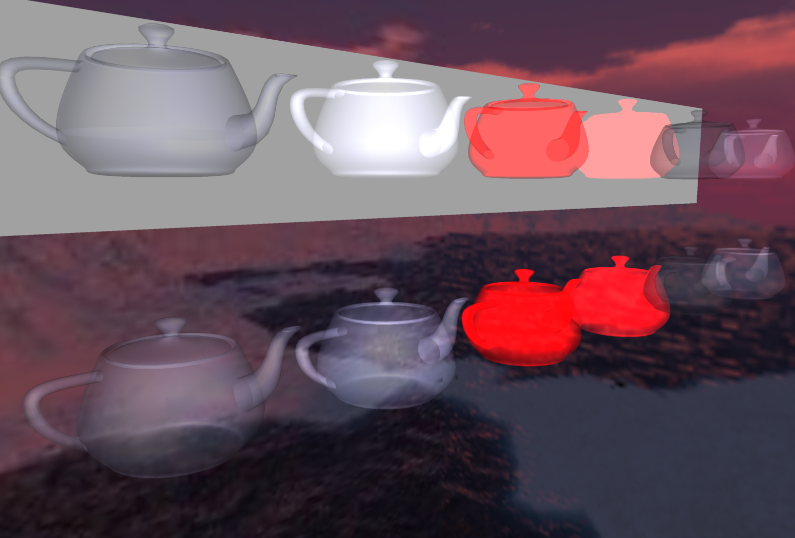
Use the BlendMode to specify how partially-transparent objects are displayed on top of other geometry.
Explanation what is a "blend mode" in 3D rendering:
-
The real-time 3D rendering APIs (like OpenGL) allow to render partially transparent objects (like "blueish glass") using blending.
-
The software first renders opaque objects, and then it renders partially transparent objects "on top" of the opaque objects. When rendering the partially transparent objects, "blending" mode is active, which means that incoming color (like "blue" from the "blueish glass" example) is mixed with the screen color (like color of the thing that was behind the glass).
( Forget for a second about the problem "what should be the rendering order". We document in blending page how does Castle Game Engine handle this. Here, assume you have good order for each screen pixel. )
Now, when rendering a partially-transparent object over something underneath, the color of the partially-transparent thing is mixed with the existing screen color. How is it mixed?
-
The standard operation is to do
new_screen_color :=
  old_screen_color * (1 - object_opacity)
  object_rgb_color * object_opacity
This is effectively a
Lerp(linear interpolation) between screen color and incoming color, using new object’s opacity (aka "alpha", aka "1 - transparency") as a factor.Is this correct (with respect to reality)? Not fully, but there is no "fully correct" equation. What we do is a poor approximation of how "partially transparent" objects work in reality. There’s no equation that will be "fully correct".
Is this "good enough"? Often, yes. Consider a thin (very transparent) glass, it can have transparency=0.9, so opacity=alpha=0.1. So the equation implies that color behind the glass mostly stays visible (it is only multiplied by 0.9) and the color of the glass mostly doesn’t disappears (it is multiplied by 0.1). This makes sense.
In contrast, a "thick" glass could have transparency=0.1, so opacity=alpha=0.1. Follow the equation to see what happens — just like in reality, color of the thick glass will now be prominent, and the thing behind will almost become invisible.
Is this problematic? Sometimes. The equation requires the partially-transparent objects to be sorted. (because imagine what happens when the object is seen through multiple layers of differently-colored glass.)
Is this standard? Yes.
-
BlendMode is X3D allows to configure this equation. All the BlendMode modes directly correspond to the glBlendFunc parameters of OpenGL.
Place this node as the Appearance.blendMode value. The exact specification of BlendMode possibilities:
Appearance {
  ... all normal Appearance fields ...
  SFNode [in,out]  blendMode  NULL  # [BlendMode]
}
BlendMode {
SFString [in,out] srcFactor "src_alpha" # [ZERO, ONE, DST_COLOR, SRC_COLOR, ONE_MINUS_DST_COLOR, ONE_MINUS_SRC_COLOR, SRC_ALPHA, ONE_MINUS_SRC_ALPHA, DST_ALPHA, ONE_MINUS_DST_ALPHA, SRC_ALPHA_SATURATE, CONSTANT_COLOR, ONE_MINUS_CONSTANT_COLOR, CONSTANT_ALPHA, ONE_MINUS_CONSTANT_ALPHA]
SFString [in,out] destFactor "one_minus_src_alpha" # [ZERO, ONE, DST_COLOR, SRC_COLOR, ONE_MINUS_DST_COLOR, ONE_MINUS_SRC_COLOR, SRC_ALPHA, ONE_MINUS_SRC_ALPHA, DST_ALPHA, ONE_MINUS_DST_ALPHA, SRC_ALPHA_SATURATE, CONSTANT_COLOR, ONE_MINUS_CONSTANT_COLOR, CONSTANT_ALPHA, ONE_MINUS_CONSTANT_ALPHA]
SFColor [in,out] color 1 1 1
SFFloat [in,out] colorTransparency 0
}An example in classic VRML/X3D encoding of using this to achieve non-standard destFactor="ONE" (this sometimes makes scene too bright, but it does not require sorting of transparent objects):
  appearance Appearance {
    material Material {
      transparency 0.5
    }
    blendMode BlendMode {
      srcFactor "SRC_ALPHA" # this srcFactor is the default actually
      destFactor "ONE"
    }
  }
BlendMode is compatible with InstantReality. We support a subset of InstantReality fields.
2.28.2. Transform by explicit 4x4 matrix (MatrixTransform node)
MatrixTransform: supported matrix field, and the standard X3DGroupingNode fields.
This is analogous to Transform node, but specifies explicit 4x4 matrix. Note that VRML 1.0 also had MatrixTransform node (we also handle it), although specified a little differently. Later VRML 97 and X3D removed the MatrixTransform node from official specification — this extension fills the gap.
Note that this node was removed from specifications for a good reason. Using MatrixTransform node means that engine must calculate matrix inverse, and sometimes even matrix decomposition (to know the proper scaling factors, and see if the scaling is uniform). This is inefficient, and sometimes also cannot be fully accurate (in case your matrix contains something more than translation/rotation/scale).
So avoid using this node, unless you have no choice — because your own input is already in the form of 4x4 matrix. Prefer using standard Transform node.
2.28.3. Events logger (Logger node)
Logger, extremely useful debugger when playing with VRML / X3D routes and events. This is based on, and should be quite compatible, with InstantReality Logger node. (Except our interpretation of logFile, which is probably quite different, see below.)
Logger : X3DChildNode {
  SFNode   [in,out]  metadata  NULL  # [X3DMetadataObject]
  SFInt32  [in,out]  level     1
  SFString []        logFile   ""
  SFBool   [in,out]  enabled   TRUE
  XFAny    [in]      write
}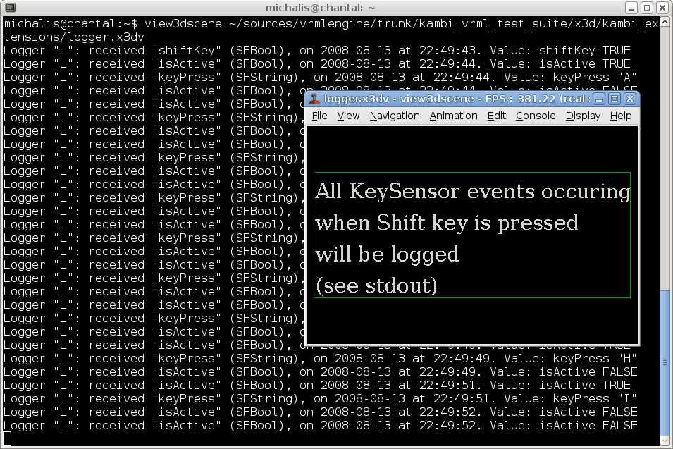
The idea is simple: whatever is sent to write input event is logged on the console. write event has special type, called XFAny (also following InstantReality) that allows to receive any VRML field type.
Other properties allow to control logging better. When enabled is false, nothing is logged. level controls the amount of logged info:
-
nothing,
-
log sending field name, type, timestamp,
-
additionally log received value,
-
additionally log sending node name, type.
logFile, when non-empty, specifies the filename to write log information to. As a security measure (we do not want to allow an author of X3D file to overwrite arbitrary files without asking user), in my implementation only the basename of the logFile matters, the file is always saved into current directory. Moreover, filename is like castle-model-viewer_logger_XXX_%d.log, where "castle-model-viewer" is the name of the program, "XXX" is the name specified in logFile, and "%d" is just next free number. This way logger output file is predictable, and should never overwrite your data.
If the logFile is empty, the output goes to the default Castle Game Engine log file for this application.
These security measures were added by my implementation — InstantReality spec simply says that logFile is the name of the file, I don’t know how they handled security problems with logFile.
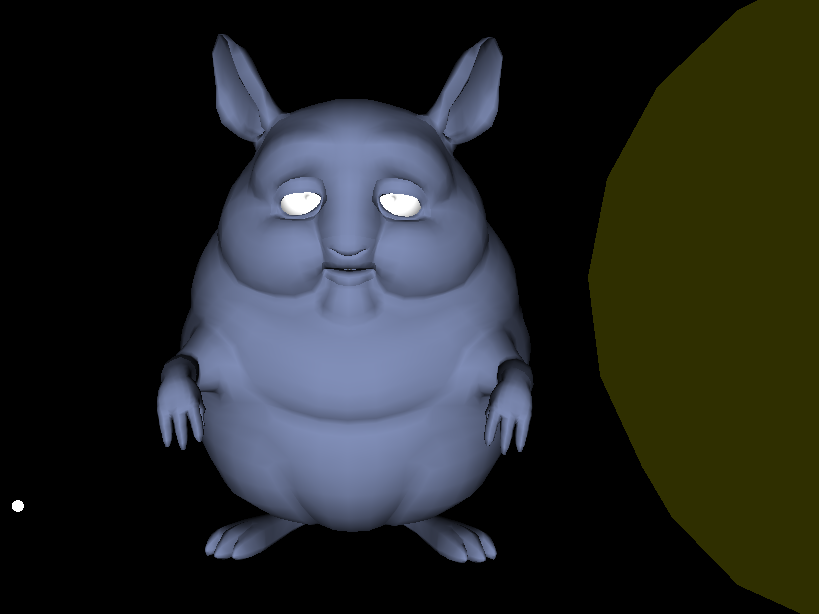
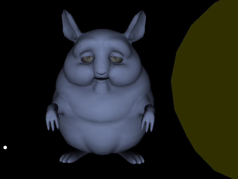
2.28.4. Teapot primitive (Teapot node)
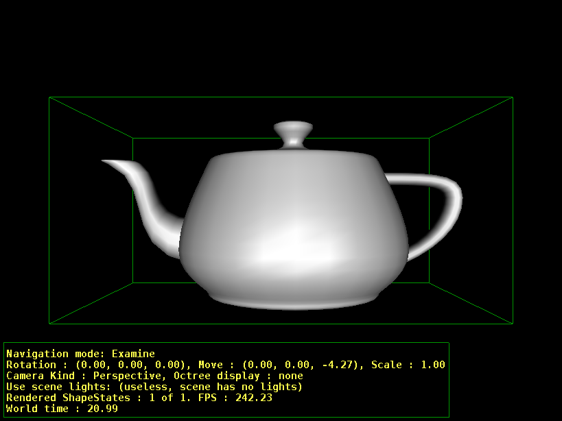
A teapot. Useful non-trivial shape for testing various display modes, shaders and such.
Compatibility with InstantReality Teapot: we support size and solid fields from InstantReality. The geometry orientation and dimensions is the same (although our actual mesh tries to be a little better :) ). Fields texCoord and manifold are our own (Kambi engine) extensions.
Teapot : X3DGeometryNode {
  SFNode  [in,out]  metadata  NULL   # [X3DMetadataObject]
  SFVec3f []        size      3 3 3
  SFBool  []        solid     TRUE
  SFBool  []        manifold  FALSE
  SFNode  [in,out]  texCoord  NULL   # [TextureCoordinateGenerator, ProjectedTextureCoordinate, MultiGeneratedTextureCoordinate]
}
The "size" field allows you to scale the teapot, much like the standard Box node. The default size (3, 3, 3) means that the longest size of teapot bounding box is 3.0 (all other sizes are actually slightly smaller). Changing size scales the teapot (assuming that size = 3 means "default size").
The "texCoord" field may contain a texture-generating node. Very useful to quickly test various texture coordinate generators (e.g. for cube environment mapping) on teapot. When texCoord is not present but texture coordinates are required (because appearance specifies a texture), we will generate default texture coords (using the same algorithm as for IndexedFaceSet).
The "solid" field has standard meaning: if true (default), it’s assumed that teapot will never be seen from the inside (and backface culling is used to speed up rendering).
The "manifold" field allows you to force teapot geometry to be correctly closed (2-manifold, where each edge has exactly 2 neighboring faces). This is useful if you want to use shadow volumes to cast shadow of this teapot.
For the sake of VRML / X3D standards, I do not really advice using this node… VRML developers should spend their time better than to implement such nodes of little practical use :), and it’s possible to make the same thing with a PROTO. But it’s useful for testing purposes.
2.28.5. Texture automatically rendered from a viewpoint (RenderedTexture node)
2.28.6. Plane (Plane node)
InstantReality Plane node. You should instead use Rectangle2D node from X3D 3.2 when possible, this is implemented only for compatibility.
Our current implementation doesn’t support anything more than size and solid fields. So it’s really equivalent to Rectangle2D inside our engine, the only difference being that Plane.solid is TRUE by default (for Rectangle2D spec says it’s FALSE by default).
2.28.7. Boolean value toggler (Toggler node)
2.28.8. Interpolate sets of floats (node VectorInterpolator)
2.28.9. Advanced shading with textures (CommonSurfaceShader)
2.29. Extensions compatible with BitManagement / BS Contact
We have a (very crude) implementation of some BitManagement specific extensions:
-
Circle(treat as standardCircle2D) -
Layer2D,Layer3D,OrderedGroup(treat as standardGroup) -
MouseSensor(does nothing, we merely parse it Ok)
2.30. VRML 1.0-specific extensions
To improve this documentation just edit this page and create a pull request to cge-www repository.