Shadow Maps
Contents:
- Intro
- Comparison with shadow volumes
- Examples
- Define lights casting shadows on everything
- Define shadow receivers
- Additional features
- Optionally specify light projection
- Optionally specify shadow map parameters (
GeneratedShadowMapnode) - Use projective texturing explicitly to map textures (
ProjectedTextureCoordinatenode) - Optionally specify shadow casters (
Appearance.shadowCaster) - No longer supported: use
GeneratedShadowMapandProjectedTextureCoordinateat each shadow-receiving shape
1. Intro
 |
 |
 |
 |
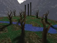
One of the shadow algorithms implemented in our engine is
shadow maps.
In the simplest case, shadow maps require that you add
just shadows TRUE to your light source in the X3D file.
Everything else is auto-detected as best as we can.
Though in many cases you will want to have more control, at least by defining
a defaultShadowMap node at the same light source.
Read on for details.
2. Comparison with shadow volumes
How shadow maps compare to shadow volumes (the other shadowing algorithm implemented in our engine):
-
Advantage: Shadow maps work with an arbitrary 3D scene. There's no need to worry about 2-manifold, like with shadow volumes.
-
Advantage: Shadow maps account for geometry with "alpha test" transparency. E.g. trees with leaves modeled by alpha-test textures. Or a fence.
-
Advantage: Shadow maps from multiple light sources cooperate perfectly. Use shadow maps with as many light sources as you want.
In contrast, shadow volumes right now can be cast from only a single light source.
-
Disadvantage and TODO:
PointLightsources do not cast shadow maps (yet). OnlySpotLightandDirectionalLightcast shadow maps.In contrast, shadow volumes work with all light sources.
-
Note: Shadow maps work independently to the shadow volumes. You can use them both at the same time, no problem. That is, you can have one light casting shadows using shadow maps, and another light casting shadows using shadow volumes.
-
Disadvantage and TODO: Shadow maps are not comfortable to control from CGE editor.
In contrast, shadow volumes can be activated by a single checkbox
Shadowsat our light source components likeTCastlePointLight.TODO: We plan a rework of shadow maps approach, to address these issues.
3. Examples
Our demo models contain many demos using shadow maps in the shadow_maps subdirectory.
Download them and open with Castle Model Viewer.
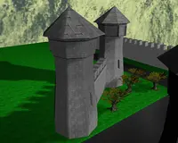
See in particular the model inside shadow_maps/castle_with_trees/, that was used for some screenshots visible on this page.
4. Define lights casting shadows on everything
In the very simplest case, to make the light source just cast shadows
on everything, set the shadows field of the light source
to TRUE.
This is the official specification:
*Light {
  ... all normal *Light fields ...
  SFBool     []            shadows     FALSE
}
This is equivalent to adding this light source to every shape's
receiveShadows field. Read on to know more details.
This is the simplest extension to enable shadows.
TODO: In the future, this field (shadows on light) and
receiveShadows field (see below) should be suitable for
other shadows implementations too.
We plan to use it for shadow volumes in the future too
(removing old shadowVolumesMain extensions and such),
and maybe ray-tracer too. shadowCaster (see below) already works
for all our shadows implementations.
If you use X3D shader nodes, like ComposedShader, be aware that your custom shaders
are then responsible for performing shadow mapps tests
(as your shaders override engine shaders).
Use instead
our compositing shaders extensions for X3D, like Effect, to write shader code that can cooperate
with our shadow maps (and other engine effects).
5. Define shadow receivers
To enable the shadows only on specific receivers, use this field:
Appearance {
  ... all normal Appearance fields ...
  MFNode     []            receiveShadows  []          # [X3DLightNode] list
}
Each light present in the receiveShadows list will cast shadows on
the given shape. That is, contribution of the light source
will be scaled down if the light is occluded at a given fragment.
We do not make any additional changes to the X3D lighting model.
The resulting fragment color is the sum of all the visible lights (visible
because they are not occluded, or because they don't cast shadows on this shape),
modified by the material emissive color and fog, following the X3D specification.
6. Additional features
The following extensions make it possible to precisely control the shadow maps (and/or projective texturing) behavior. An example usage:
DEF MySpot SpotLight {
  location 0 0 10
  direction 0 0 -1
  projectionNear 1
  projectionFar 20
  defaultShadowMap GeneratedShadowMap {
    update "ALWAYS"
    size 1024
  }
}

Shape {
  appearance Appearance {
    receiveShadows MySpot
    material Material { }
  }
  geometry IndexedFaceSet {
    # ... other IndexedFaceSet fields
  }
}
The shadow map will be used by the engine to determine whether the associated light is obscured or not at each screen pixel. Our default shaders will make it look nice out-of-the-box.
6.1. Optionally specify light projection
The motivation behind the extensions in this section is that we want to use light sources as cameras. This means that lights need additional parameters to specify projection details.
To every X3D light node (DirectionalLight, SpotLight,
PointLight) we add new fields:
*Light {
  ... all normal *Light fields ...
  SFFloat    [in,out]      projectionNear        0           # must be >= 0
  SFFloat    [in,out]      projectionFar         0           # must be > projectionNear, or = 0
  SFVec3f    [in,out]      up                    0 0 0
  SFNode     []            defaultShadowMap      NULL        # [GeneratedShadowMap]
}
The fields projectionNear and projectionFar specify the near
and far values for the projection used when rendering to the shadow map texture.
These are distances from the light position, along the light direction.
You should always try to make projectionNear as large as possible
and projectionFar as small as possible,
this will make depth precision better (keeping projectionNear large
is more important for this). At the same time, your projection range
must include all your shadow casters.
The field up is the "up" vector of the light camera when capturing
the shadow map. This is used only with non-point lights
(DirectionalLight and SpotLight).
Although we know the direction of the light source,
but for shadow mapping we also need to know the "up" vector to have camera
parameters fully determined.
You usually don't need to provide the "up" vector value in the file.
We intelligently guess (or fix your provided value) to be always Ok.
The "up" value is processed like this:
- If up = zero (default), assume up := +Y axis (0,1,0).
- If up is parallel to the direction vector, set up := arbitrary vector orthogonal to the direction.
- Finally, make sure up vector is exactly orthogonal to the direction (eventually rotating it slightly).
These properties are specified at the light node, because both shadow map generation and texture coordinate calculation must know them, and use the same values (otherwise results would not be of much use).
The field defaultShadowMap allows to adjust shadow map parameters.
It is used only when the light actually casts shadows using shadow maps
(so the light is listed among some shape receiveShadows,
or the light has shadows field set TRUE).
Leaving the defaultShadowMap as NULL means that an
implicit shadow map with default browser settings should be generated
for this light. This must behave like update was set to
ALWAYS.
DirectionalLight gets additional fields to specify orthogonal
projection rectangle (projection XY sizes) and location for
the light camera. Although directional light is conceptually at infinity
and doesn't have a location, but for making a texture projection
we actually need to define the light's location.
DirectionalLight {
  ... all normal *Light fields ...
  SFVec4f    [in,out]      projectionRectangle   0 0 0 0     #
      # left, bottom, right, top (order like for OrthoViewpoint.fieldOfView).
      # Must be left < right and bottom < top, or all zero
  SFVec3f    [in,out]      projectionLocation    0 0 0       # affected by node's transformation
}
When projectionNear, projectionFar, up,
projectionRectangle have (default) zero values, then some sensible
values are automatically calculated for them by the browser.
projectionLocation will also be automaticaly adjusted,
if and only if projectionRectangle is zero.
This will work perfectly for shadow receivers marked by the
receiveShadows field.
 |
 |
SpotLight gets additional field to explicitly specify a perspective projection angle.
SpotLight {
  ... all normal *Light fields ...
  SFFloat    [in,out]      projectionAngle       0
}
Leaving projectionAngle at the default zero value is equivalent
to setting projectionAngle to 2 * cutOffAngle.
This is usually exactly what is needed.
Note that the projectionAngle is
the vertical and horizontal field of view for the square texture,
while cutOffAngle is the angle of the half of the cone
(that's the reasoning for *2 multiplier).
Using 2 * cutOffAngle as projectionAngle
makes the perceived light cone fit nicely inside the projected
texture rectangle. It also means that some texture space is essentially
wasted — we cannot perfectly fit a rectangular texture into a circle shape.
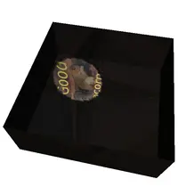
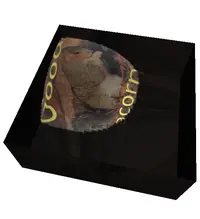
Images on the right show how a light cone fits within the projected texture.
6.2. Optionally specify shadow map parameters (GeneratedShadowMap node)
Now that we can treat lights as cameras, we want to render shadow maps from the light sources. The rendered image is stored as a texture, represented by a new node:
GeneratedShadowMap : X3DTextureNode {
  SFNode     [in,out]      metadata         NULL                  # [X3DMetadataObject]
  SFString   [in,out]      update           "NONE"                # ["NONE"|"NEXT_FRAME_ONLY"|"ALWAYS"]
  SFInt32    []            size             128
  SFFloat    [in,out]      scale            4.0
  SFFloat    [in,out]      bias             4.0
}
 |
 |
The update field determines how often the shadow map should be
regenerated. It is analogous to the update field in the standard
GeneratedCubeMapTexture node.
"NONE"means that the texture is not generated. It is the default value (because it's the most conservative, so it's the safest value)."ALWAYS"means that the shadow map must be always accurate. Generally, it needs to be generated every time shadow caster's geometry noticeably changes. The simplest implementation may just render the shadow map at every frame."NEXT_FRAME_ONLY"says to update the shadow map at the next frame, and afterwards change the value back to"NONE". This gives the author an explicit control over when the texture is regenerated, for example by sending"NEXT_FRAME_ONLY"values by aScriptnode.
The field size gives the size of the (square) shadow map texture
in pixels.
 |
 |
 |
 |
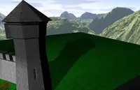
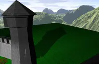
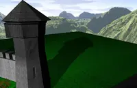
Fields scale and bias are used
to offset the scene rendered to the shadow map.
This avoids the precision problems inherent in the shadow maps comparison.
In short, increase them if you see
a strange noise appearing on the shadow casters (but don't increase them too much,
or the shadows will move back).
You may increase the bias a little more
carelessly (it is multiplied by a constant implementation-dependent offset,
that is usually something very small).
Increasing the scale has to be done a little more carefully
(it's effect depends on the polygon slope).
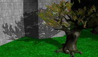
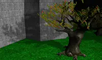
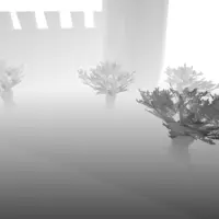
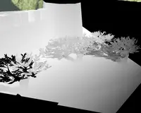
Images on the right show the effects of various
scale and bias values.
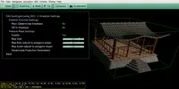
You can adjust the bias, scale
and size interactively in Castle Model Viewer.
Using the Edit->Lights Editor feature, you can configure
the defaultShadowMap parameters for a given light,
and immediately see the results.
For an OpenGL implementation
that offsets the geometry rendered into the shadow map,
scale and bias are an obvious parameters (in this order)
for the glPolygonOffset call.
Other implementations are free to ignore these parameters, or derive
from them values for their offset methods.
For OpenGL implementations, the most natural format for a shadow map texture
is the GL_DEPTH_COMPONENT (see ARB_depth_texture).
This makes it ideal for typical shadow map operations.
For GLSL shader, this is best used with sampler2DShadow
(for spot and directional lights) and
samplerCubeShadow (for point lights).
Usage notes: You should place GeneratedShadowMap node inside light's defaultShadowMap field.
Variance Shadow Maps notes:
If you turn on Variance Shadow Maps (e.g. by view3dscene menu View -> Shadow Maps -> Variance Shadow Maps), then
the generated textures are a little different.
If you used the simple "receiveShadows" field, everything is taken
care of for you. But if you use lower-level nodes and write your own
shaders, you must understand the differences:
for VSM, shadow maps are treated always as sampler2D, with the first
two components being E(depth) and E(depth^2).
See the paper about Variance Shadow Maps.
6.3. Use projective texturing explicitly to map textures (ProjectedTextureCoordinate node)
We add a new ProjectedTextureCoordinate node:
ProjectedTextureCoordinate : X3DTextureCoordinateNode {
  SFNode     [in,out]      projector   NULL        # [SpotLight, DirectionalLight, X3DViewpointNode]
}
This node generates texture coordinates, much like the standard
TextureCoordinateGenerator node.
More precisely, a texture coordinate (s, t, r, q) will be generated for a fragment
that corresponds to the shadow map pixel on the position (s/q, t/q),
with r/q being the depth (distance from the light source or the viewpoint,
expressed in the same way as depth buffer values are stored in the shadow map).
In other words, the generated texture coordinates will contain the actual
3D geometry positions, but expressed in the projector's frustum coordinate system.
This cooperates closely with the shadow map test.
This can be used in all situations when the light or the viewpoint act like
a projector for a 2D texture. For shadow maps, projector should be
a light source.
Note that the light node instanced inside the
ProjectedTextureCoordinate.projector field
(or deprecated GeneratedShadowMap.light field)
isn't considered a normal light, that is it doesn't shine anywhere.
It should be defined elsewhere in the scene to actually
act like a normal light. Moreover, it should not be
instanced many times (outside of GeneratedShadowMap.light
and ProjectedTextureCoordinate.projector), as then it's
unspecified from which view we will generate the shadow map.
When a perspective Viewpoint is used as the projector,
we need an additional rule. That's because the viewpoint doesn't explicitly
determine the horizontal and vertical angles of view, so it doesn't precisely
define a projection. We resolve it as follows: when the viewpoint
that is not currently bound is used as a projector,
we use Viewpoint.fieldOfView for both the horizontal and vertical
view angles. When the currently bound viewpoint is used,
we follow the standard Viewpoint specification for calculating
view angles based on the Viewpoint.fieldOfView and the window sizes.
(TODO: our current implementation doesn't treat currently bound
viewpoint this way.)
We feel that this is the most useful behavior for scene authors.
When the geometry uses a user-specified vertex shader, the implementation
should calculate correct texture coordinates on the CPU.
This way shader authors still benefit from the projective texturing extension.
If the shader author wants to implement projective texturing inside the shader,
he is of course free to do so, there's no point in using
ProjectedTextureCoordinate at all then.
Note that this is not suitable for point lights. Point lights do not have a direction, and their shadow maps can no longer be single 2D textures. Instead, they must use six 2D maps. For point lights, it's expected that the shader code will have to do the appropriate texture coordinate calculation: a direction to the point light (to sample the shadow map cube) and a distance to it (to compare with the depth read from the texture).
Deprecated: In older engine versions, instead of this node
you had to use TextureCoordinateGenerator.mode = "PROJECTION"
and TextureCoordinateGenerator.projectedLight. This is still
handled (for compatibility), but should not be used in new models.
6.4. Optionally specify shadow casters (Appearance.shadowCaster)
By default, every Shape in the scene casts a shadow.
This is the most common setup for shadows.
However it's sometimes useful to explicitly
disable shadow casting (blocking of the light) for some tricky shapes.
For example, this is usually desired for shapes that visualize
the light source position.
For this purpose we extend the Appearance node:
Appearance {
  ... all Appearance fields ...
  SFBool     [in,out]      shadowCaster     TRUE
}
Note that if you disable shadow casting on your shadow receivers
(that is, you make all the objects only casting or only receiving the shadows,
but not both) then you avoid some offset problems with shadow maps. The bias
and scale parameters of the GeneratedShadowMap
become less crucial then.
This is honoured by all our shadow implementations: shadow volumes, shadow maps (that is, both methods for dynamic shadows in OpenGL) and also by our ray-tracers.
Note that shadow maps cannot deal with transparency by alpha-blending. The objects using blending are never shadow casters, for shadow maps and ray-tracers.
6.5. No longer supported: use GeneratedShadowMap and ProjectedTextureCoordinate at each shadow-receiving shape
For original reasoning behind these extensions, see also my paper Shadow maps and projective texturing in X3D (presented at Web3D 2010 conference). The slides from the presentation are also available.
Note that the advised usage of shadow maps
(section 4 of the paper) shifted a bit since the paper was written.
The PDF paper talks about "low-level nodes usage", which has been deprecated and later removed. The described nodes are still supported but with different usage:
now, the GeneratedShadowMap should only be placed in defaultShadowMap field of the light node, and ProjectedTextureCoordinate should only be used for projective texturing (not for shadow maps).
Note that the paper, and so portions of the text below, are Copyright 2010 by ACM, Inc. See the link for details, in general non-commercial use is fine, but commercial use usually requires asking ACM for permission. This is a necessary exception from my usual rules of publishing everything on GNU GPL.
The approach described below was deprecated for a long time, and finally it will no longer work after this refactor.
You can place GeneratedShadowMap node
in the Appearance.texture (possibly inside MultiTexture
node).
In this case you also need to specify texture coordinates using an explicit
ProjectedTextureCoordinate node.
An example is below:
DEF MySpot SpotLight {
  location 0 0 10
  direction 0 0 -1
  projectionNear 1
  projectionFar 20
}

Shape {
  appearance Appearance {
    material Material { }
    texture GeneratedShadowMap {
      light USE MySpot
      update "ALWAYS"
      size 1024
    }
  }
  geometry IndexedFaceSet {
    texCoord ProjectedTextureCoordinate {
      projector USE MySpot
    }
    # ... other IndexedFaceSet fields
  }
}
Note that view3dscene's menu items View -> Shadow Maps -> ... does not affect the shadow map in this case.
This approach is deprecated now. Reasons:
Placing the shadow map in
Appearance.textureis not really consistent with normalAppearance.texturetreatment, since the shadow map affects the rendering in a special way (it "masks" the particular light source contribution).Shadow map does not mix the fragment color like
Appearance.textureshould (that scales theMaterial.diffuseColor,PhysicalMaterial.baseColororUnlitMaterial.emissiveColor).Placing the shadow map here doesn't work with CommonSurfaceShader, as it has it's own textures.
CommonSurfaceShader.diffuseTexturehides theAppearance.texture.