| 5.5. Texture effects | ||
|---|---|---|
 | Chapter 5. Extending the shaders with plugs |  |
Just like the light sources, also each texture node may define its own effects:
X3DTextureNode

MFNode [] effects [] # Effect
X3DTextureNode is an ancestor for all the standard texture nodes,
like the ImageTexture. This allows to modify any X3D texture
by shader effects.
A plug texture_color may be used to change the texture color,
taking into account the current texture coordinates and other information.
A new X3D node ShaderTexture is available for creating
procedural textures using the GPU shading languages.
The texture contents are not stored anywhere (not even on GPU)
and the renderer does not manage any texture resources.
From a GPU point of view, there is no texture.
There is only a shader function that generates colors
based on some vectors. By wrapping such function inside
the ShaderTexture node, it can be treated exactly like other textures
in the scene. In particular, texture coordinates
(explicit or generated) can be comfortably provided
for the procedural texture.
Effectively, it behaves like a normal texture node, with all the related
X3D features.
The new texture node specification:
ShaderTexture : X3DTextureNode

MFNode [] effects [] # Effect

SFString [] defaultTexCoord "BOUNDS2D"
  # ["BOUNDS2D"|"BOUNDS3D"]
Actually, the effects field is already defined in
the base X3DTextureNode class mentioned previously.
It is repeated here only for completeness.
An effect overriding the texture_color plug
should be included, otherwise texture colors are undefined.
Our implementation
sets the default texture color to pink (RGB(1, 0, 1)), so it stands out,
reminding author to override it.
The texture coordinates, or the algorithm to generate them,
can be explicitly specified, just like for any other texture in X3D.
This is done by placing any X3DTextureCoordinateNode
node inside the geometry texCoord field.
Both explicit texture coordinate lists (TextureCoordinate,
TextureCoordinate3D, TextureCoordinate4D)
as well as the coordinate generator nodes
(like TextureCoordinateGenerator and
ProjectedTextureCoordinate) are allowed.
Note that projective texture mapping
by the ProjectedTextureCoordinate
is also our X3D extension, see [X3D Shadow Maps].
When the texture coordinates are not given,
the defaultTexCoord field determines how they are generated:
"BOUNDS2D"generates 2D texture coordinates, adapting to the two largest bounding box sizes. The precise behavior of"BOUNDS2D"follows the X3DIndexedFaceSetspecification.This is most comfortable when the texture color depends only on the XY components of the texture coordinate. The 3rd texture coordinate component is always 0, and the 4th component is always 1.
"BOUNDS3D"generates 3D texture coordinates. The texture coordinates are adapted to all three bounding box sizes, precisely following X3D specification section "Texture coordinate generation for primitive objects" of the Texturing3D component.This is most suitable for true 3D textures. The 4th texture coordinate component can be ignored. Or the 4D vector may be treated as homogeneous, as
"BOUNDS3D"will always set the 4th component to 1.
The "BOUNDS*" names are consistent
with another extension of our engine. We allow
the same values to be used in the TextureCoordinateGenerator.mode field.
See [X3D TexCoord Bounds].
In the end, the idea is that using a ShaderTexture
should be as comfortable as any other texture node.
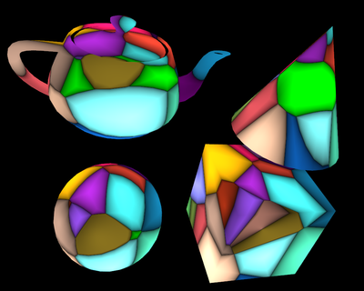
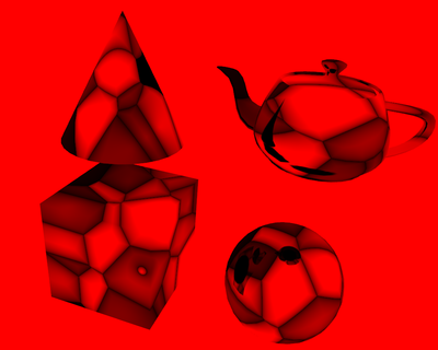
As an example, we present an outline of a procedural texture
code using the cellular texturing idea.
This is a nice approach to computing segmented textures, resembling
various combinations of Voronoi diagrams.
We override the PLUG_texture_color
to calculate a feature point that is closest in 3D space
to our current texture coordinate. The distance to this feature point,
combined with the distance to the next-closest feature point, can be combined
to achieve interesting visual effects.
ShaderTexture {
  effects Effect {
    language "GLSL"
    parts EffectPart {
      type "FRAGMENT"
      url "data:text/plain,
        #version 120

        void PLUG_texture_color(inout vec4 texture_color,
          const in vec4 tex_coord)
        {
          const int count = ...;
          const vec3 feature_points[count] = vec3[count](...);
          const vec3 feature_colors[count] = vec3[count](...);

          float[count] distances;
          int closest0, closest1;
          for (int i = 0; i < count; i ++)
          {
            distances[i] = distance(vec3(tex_coord), feature_points[i]);
            /* ...
             Update closest0 to indicate the closest feature point,
             that is distances[closest0] is smallest among all distances.
             Update closest1 to index of the 2nd-closest feature point.
            */
          }

          texture_color.rgb = pow(distances[closest1] -
            distances[closest0], 0.3) * 2.0 * feature_colors[closest0];
        }"
    }
  }
  defaultTexCoord "BOUNDS3D"
}
Note that this is a very simple approach to implementing cellular texturing. Much more optimal implementation is possible. There are also many variations that achieve different visual appeal. See our engine demo models (http://castle-engine.sourceforge.net/demo_models.php) for a complete and working implementation.
Figure 5.4, “Cellular texturing” shows this texture used in various settings. It can be combined with other textures without any effort — in this case, we show it combined with a cube map texture that simulates a mirror.
Figure 5.4. Cellular texturing
 |
 |
For textures other than the ShaderTexture,
when the texture_color plugs are called,
the internal shaders have already calculated the initial texture
color by actually sampling the texture image. This is useful if you
want to modify this color. If you'd rather ignore the normal
sampled color, and always override it with your own, consider using
the special ShaderTexture node instead. Using
a normal texture node (like ImageTexture) for this
would be uncomfortable, as you would have to load a dummy texture image,
and the shaders could (depending on optimization) waste some time
on calculating a color that will be actually ignored later.
Note that in all cases (effects at ImageTexture,
at ShaderTexture, etc.) you can always use additional
textures inside the effect. Just like inside a standard ComposedShader,
you can declare an SFNode field inside an Effect
to pass any texture node to the shader as a uniform value.
This allows to combine any number of textures inside an effect.
The only difference
between ShaderTexture and other textures is what the system
does automatically for you, that is what color is passed
to the first texture_color plug.
The shader effects for textures are calculated at each screen fragment,
not at each texel. So the effects are not concerned with the texture size
or texture filtering options. The texture_color plug
receives the interpolated texture coordinates.
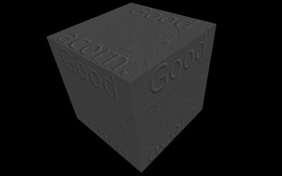
Figure 5.6, “Texture effects are not concerned with the texture resolution”
shows a blue arc drawn on a texture by our effect.
The arc border is perfectly smooth, without any concern about
the pixel resolution of the underlying texture.

| |  | |
| 5.4. Light sources effects |  | Chapter 6. Extensions for geometry shaders |