(Outdated) Overview of the Castle Game Engine and VRML 1.0
Copyright © 2006, 2007, 2008, 2009, 2010, 2011, 2012, 2013, 2014, 2022 Michalis Kamburelis
You can redistribute and/or modify this document under the terms of the GNU General Public License as published by the Free Software Foundation; either version 2 of the License, or (at your option) any later version.
Table of Contents
- Goals
- 1. Overview of VRML
- 2. Scene Manager
- 3. Reading, writing, processing VRML scene graph
- 4. Octrees
- 5. Ray-tracer rendering
- 6. OpenGL rendering
- 7. Animation
- 8. Shadow Volumes
- 9. Links
List of Figures
- 1.1. VRML 1.0 sphere example
- 1.2. VRML 2.0 sphere example
- 1.3. Cylinder example, rendered in wireframe mode (because it's unlit, non-wireframe rendering would look confusing)
- 1.4. VRML points example: yellow point at the bottom, blue point at the top
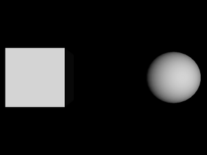
- 1.5. A cube and a sphere in VRML 1.0
- 1.6. An unlit box and a sphere in VRML 2.0
- 1.7. A box and a translated sphere
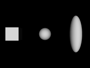
- 1.8. A box, a translated sphere, and a translated and scaled sphere
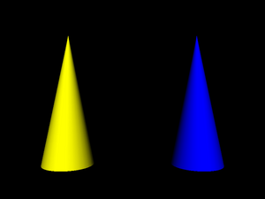
- 1.9. Two cones with different materials
- 1.10. A box and a translated sphere using the same texture
- 1.11. Three columns of three spheres
- 1.12. Faces, lines and point sets rendered using
the same
Coordinatenode - 1.13. Spheres with various material in VRML 1.0
- 1.14. An example how properties “leak out” from various grouping nodes in VRML 1.0
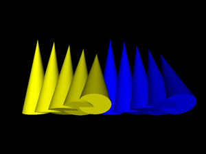
- 1.15. Our earlier example of reusing cone inlined a couple of times, each time with a slight translation and rotation
- 1.16. Textured cube with various texture transformations
- 1.17. Viewpoint defined for our previous example with multiplied cones
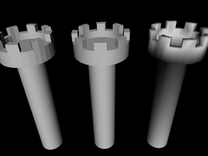
- 1.18. Three towers with various
creaseAnglesettings - 2.1. Three 3D objects are rendered here: precalculated dinosaur animation, scripted (could be interactive) fountain animation, and static tower.
- 2.2. Simple scene, viewed from various viewports simultaneously.
- 2.3. Interactive scene, with shadows and mirors, viewed from various viewports.
- 4.1. A sample octree constructed for a scene with two boxes and a sphere
- 4.2. A nasty case when a box is considered to be colliding with a frustum, but in fact it's outside of the frustum
- 5.1. lets_take_a_walk scene, side view
- 5.2. lets_take_a_walk scene, top view
- 5.3. Generated ground texture
- 5.4. lets_take_a_walk scene, with ground texture. Side view
- 5.5. lets_take_a_walk scene, with ground texture. Top view.
- 6.1. All the trees visible on this screenshot are actually the same tree model, only moved and rotated differently.
- 6.2. The correct rendering of the trees with volumetric fog
- 6.3. The wrong rendering of the trees with volumetric fog, if we would use the same arrays/VBO (containing fog coordinate for each vertex) for both trees.
- 6.4. Rendering without the fog (camera frustum culling is used)
- 6.5. Rendering with the fog (only objects within the fog visibility range need to be rendered)
- 6.6. The ghost creature on this screenshot is actually very close to the player. But it's transparent and is rendered incorrectly: gets covered by the ground and trees.
- 6.7. The transparent ghost rendered correctly: you can see that it's floating right before the player.
- 6.8. Material transparency with random stipples
- 6.9. Material transparency with regular stipples
- 8.1. Fountain level, no shadows
- 8.2. Fountain level, shadows turned on
- 8.3. Fountain level, edges marked
- 8.4. Fountain level, only edges
- 8.5. Ghost shadows
- 8.6. Lack of shadows, problem analogous to ghost shadows
- 8.7. A cylinder capped at the top, open at the bottom
- 8.8. Cylinder open at the bottom with shadow quads
- 8.9. Cylinder open at the bottom with shadow edges
- 8.10. Good shadow from a single triangle
- 8.11. Good shadow from a single triangle, with shadow volumes drawn
- 8.12. Bad shadow from a single triangle
This document describes the implementation of a 3D engine based on the VRML and X3D languages.
The VRML language is used to define 3D worlds. X3D is simply VRML 3.0, also supported by our engine (since May 2008). We will have some introduction to the language in Chapter 1, Overview of VRML. VRML has many advantages over other 3D languages:
The specification of the language is open.
The language is implementation-neutral, which means that it's not “tied” to any particular rendering method or library. It's suitable for real-time rendering (e.g. using OpenGL or DirectX), it's also suitable for various software methods like ray-tracing. This neutrality includes the material and lighting model described in VRML 2.0 specification.
Inventor, an ancestor of the VRML, lacked such neutrality. Inventor was closely tied to the OpenGL rendering methods, including the OpenGL lighting model.
The language is quite popular and many 3D authoring programs can import and export models in this format. Some well-known open-source 3D modeling programs that can export to VRML are Blender and Art Of Illusion. White Dune is a modeller especially oriented towards VRML.
The language can describe geometry of 3D objects with all typical properties like materials, textures and normal vectors. More advanced features like multi-texturing, environment cube map texturing, shaders (in GLSL, NVidia Cg, HLSL) are also available in newest version (X3D).
The language is not limited to 3D objects. Other important environment properties, like lights, the sky, the fog, viewpoints, collision properties and many other can be expressed. Events mechanism allows to describe animations and user interactions with the scene.
The language is easy to extend. You can easily add your own nodes and fields (and I did, see the list of my VRML extensions).
Implementation goals were to make an engine that
Uses VRML / X3D. Some other 3D file formats are also supported (like 3DS, MD3, Wavefront OBJ and Collada) by silently converting them to VRML/X3D graph.
Allows to make a general-purpose VRML browser. See view3dscene.
Allows to make more specialized programs, that use the engine and VRML models as part of their job. For example, a game can use VRML models for various parts of the world:
Static environment parts (like the ground and the sky) can be stored and rendered as one VRML model.
Each creature, each item, each “dynamic” object of the world (door that can open, building that can explode etc.) can be stored and rendered as a separate VRML model.
When rendering, all these VRML objects can be rendered within the same frame, so that user sees the complete world with all objects.
Example game that uses my engine this way is “The Castle”.
Using the engine should be as easy as possible, but at the same time OpenGL rendering must be as fast as possible. This means that a programmer gets some control over how the engine will optimize given VRML model (or part of it). Different world parts may require entirely different optimization methods:
static parts of the scene,
parts of the scene that move (or rotate or scale etc.) only relatively to the static parts,
parts of the scene that frequently change inside (e.g. a texture changes or creature's arm rotates).
All details about optimization and animation methods will be given in later chapters (see Chapter 6, OpenGL rendering and Chapter 7, Animation).
The primary focus of the engine was always on 3D games, but, as described above, VRML models can be used and combined in various ways. This makes the engine suitable for various 3D simulation programs (oh, and various game types).
The engine is free open-source software (licensed on GNU General Public License).
Developed in object-oriented language. For me, the language of choice is ObjectPascal, as implemented in the Free Pascal compiler.
Table of Contents
This chapter is an overview of VRML concepts. It describes the language from the point of view of VRML author. It teaches how a simple VRML files look like and what are basic building blocks of every VRML file. It's intended to be a simple tutorial into VRML, not a complete documentation how to write VRML files. If you want to learn how to write non-trivial VRML files you should consult VRML specifications.
This chapter also describes main differences between VRML 1.0, 2.0 (also known as VRML 97) and 3.0 (more widely known as X3D). Our engine currently handles all these VRML versions. However, at the time of initial writing of this document, our engine supported only VRML 1.0 and basic 2.0, so more advanced and interesting VRML 2.0 and X3D concepts are only outlined at the end of this chapter — maybe this will be enhanced some day.
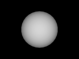
VRML files are normal text files, so they can be viewed and edited in any text editor. Here's a very simple VRML 1.0 file that defines a sphere:
#VRML V1.0 ascii

Sphere { }
The first line is a header. It's purpose is to identify
VRML version and encoding used. Oversimplifying things a little,
every VRML 1.0 file will start with the exact same line:
#VRML V1.0 ascii.
After the header comes the actual content.
Like many programming languages, VRML language is a free-form
language, so the amount of whitespace in the file doesn't really matter.
In the example file above we see a declaration of a node
called Sphere. “Nodes” are the building
blocks of VRML: every VRML file specifies a directed graph of nodes.
After specifying the node name (Sphere),
we always put an opening brace (character {),
then we put a list of fields and
children nodes of our node,
and we end the node by a closing brace (character }).
In our simple example above, the Sphere
node has no fields specified and no children nodes.
The geometry defined by this VRML file is a sphere centered at the origin of coordinate system (i.e. point (0, 0, 0)) with a radius 1.0.
Why the sphere is centered at the origin?
Spheres produces by a
Spherenode are always centered at the origin — that's defined by VRML specifications. Don't worry, we can define spheres centered at any point, but to do this we have to use other nodes that will move ourSpherenode — more on this later.Why the sphere radius is 1.0?
This is the default radius of spheres produced by
Spherenode. We could change it by using theradiusfield of aSpherenode — more on this later.
Since the material was not specified, the sphere will use the default material properties. These make a light gray diffuse color (expressed as (0.8, 0.8, 0.8) in RGB) and a slight ambient color ((0.2, 0.2, 0.2) RGB).
An equivalent VRML 2.0 file looks like this:
#VRML V2.0 utf8

Shape {
  geometry Sphere { }
}
As you can see, the header line is now different. It indicates VRML version as 2.0 and encoding as utf8 [1].
In VRML 2.0 we can't directly use a Sphere
node. Instead, we have to define a Shape node
and set it's geometry field to our desired
Sphere node. More on fields and children nodes
later.
Actually, our VRML 2.0 example is not equivalent to VRML 1.0 version: in VRML 2.0 version sphere is unlit (it will be rendered using a single white color). It's an example of a general decision in VRML 2.0 specification: the default behavior is the one that is easiest to render. If we want to make the sphere lit, we have to add a material to it — more on this later.

Every VRML node has a set of fields.
A field has a name, a type, and a default value. For example,
Sphere node has a field named radius,
of type SFFloat, that has a default value of 1.0.
There are many field types defined by VRML specification. Each field type specifies a syntax for field values in VRML file, and sometimes it specifies some interpretation of the field value. Example field types are:
SFFloat,SFDouble,SFTimeA float value. Syntax is identical to the syntax used in various programming languages, for example
3.1415926or12.5e-3.X3D added
SFDoubletype, which should be stored and processed with at least double precision.And there's the
SFTimefield type. It's syntax and internals are equivalent toSFDouble, but it has an added semantic: it specifies a time period or a point in time. In the latter case, this is the number of seconds passed since the Unix epoch (00:00:00 UTC on 1 January 1970). Although for single-player games, where time is not necessarily tied to the real-world time, sometimes other interpretations are useful, see my “VRML / X3D time origin considered uncomfortable” article.SFLong(in VRML 1.0),SFInt32(in VRML 2.0)A 32-bit integer value. As you can see, the name was changed in VRML 2.0 to indicate clearly the range of allowed values.
SFBoolA boolean value. Syntax: one word, either
FALSEorTRUE. Note that VRML is case-sensitive. In VRML 1.0 you could also write the number 0 (forFALSE) or 1 (forTRUE), but this additional syntax was removed from VRML 2.0 (since it's quite pointless).SFVec2f,SFVec3f,SFVec4fVector of 2, 3 or 4 floating point values. Syntax is to write them as a sequence of
SFFloatvalues, separated by whitespace. The specification doesn't say how these vectors are interpreted: they can be positions, they can be directions etc. The interpretation must be given for each case when some node includes a field of this type.The 4-component
SFVec4fwas added in X3D. X3D also added double-precision versions of these vectors:SFVec2d,SFVec3d,SFVec4d.SFColor,SFColorRGBA(X3D)Syntax of
SFColoris exactly likeSFVec3f, but this field has a special interpretation: it's an RGB (red, green, blue) color specification. Each component must be between 0.0 and 1.0. For example, this is a yellow color:1 1 0.X3D adds also 4-component type
SFColorRGBA, that adds alpha (opacity) value to the RGB color.SFRotationFour floating point values specifying rotation around an axis. First three values specify an axis, fourth value specifies the angle of rotation (in radians).
SFMatrix3f(X3D),SFMatrix3d(X3D),SFMatrix4f(X3D),SFMatrix4d(X3D),SFMatrix(VRML 1.0)3x3 and 4x4 matrix types, in single or double precision. Especially useful when transferring matrix data to GPU shaders.
VRML 1.0 had also a type named just
SFMatrix, this was equivalent to X3D'sSFMatrix4f.SFImageThis field type is used to specify image content for
PixelTexturenode in VRML 2.0 (Texture2node in VRML 1.0). This way you can specify texture content directly in VRML file, without the need to reference any external file. You can create grayscale, grayscale with alpha, RGB or RGB with alpha images this way. This is sometimes comfortable, when you must include everything in one VRML file, but beware that it makes VRML files very large (because the color values are specified in plain text, and they are not compressed in any way). See VRML specification for exact syntax of this field.An alternative, often better method to “inline” some file content inside VRML/X3D file is to use the data: URI. This allows you to inline file contents everywhere where normallny URI is accepted (for example, you can use normal
ImageTextureand it'surlfield), so it's more general solution. It's also more standard (not specific to VRML/X3D at all). And it allows to place compressed data (e.g. compressed PNG, JPG or any other file format, as specified by the mime type inside URI). Although compressed data will have to be encoded in base64, so it's not storage-optimal, but still it's usually much better thanSFImagenon-compressed format.The
data:URI is supported by most modern VRML/X3D browsers (including every program using our engine). So it's usually preferred over usingSFImage, for all but the tiniest images.SFStringA string, enclosed in double quotes. If you want to include double quote in a string, you have to precede it with the backslash (
\) character, and if you want to include the backslash in a string you have to write two backslashes. For example:"This is a string." "\"To be or not to be\" said the man." "Windows filename is c:\\3dmodels\\tree.wrl"Note that in VRML 2.0 this string can contain characters encoded in utf8 [2].
SFNodeThis is a special VRML 2.0 field type that contains other node as it's value (or a special value
NULL). More about this in Section 1.3, “Children nodes”.
All names of field types above start with SF,
which stands for “single-value field”. Most of these field types
have a counterpart, “multiple-value field”, with a name
starting with MF. For example MFFloat,
MFLong, MFInt32,
MFVec2f and MFVec3f.
The MF-field value is a sequence of any number
(possibly zero) of single field values. For example,
MFVec3f field specifies any number of 3-component
vectors and can be used to specify a set of 3D positions.
Syntax of multiple-value fields is:
An opening bracket (
[).A list of single field values separated by commas (in VRML 1.0) or whitespaces (in VRML 2.0). Note that in VRML 2.0 comma is also a whitespace, so if you write commas between values your syntax is valid in all VRML versions.
A closing bracket (
]). Note that you can omit both brackets if your MF-field has exactly one value.
Each node has a set of fields given by VRML specification. VRML file can specify value of some (maybe all, maybe none) node's fields. You can always leave the value of a field unspecified in VRML file, and it always is equivalent to explicitly specifying the default value for given field.
VRML syntax for specifying node fields is simple:
within node's braces ({ and })
place field's name followed by field's value.
Let's see some examples of specifying field values.
Sphere node has a field named
radius of type SFFloat
with a default value 1.0. So the file below is exactly
equivalent to our first sphere example in previous section:
#VRML V1.0 ascii

Sphere {
  radius 1
}
And this is a sphere with radius 2.0:
#VRML V1.0 ascii

Sphere {
  radius 2
}
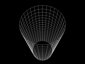
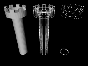
Here's a VRML 2.0 file that specifies a cylinder that should be rendered
without bottom and top parts (thus creating a tube), with a
radius 2.0 and height 4.0. Three SFBool
fields of Cylinder are used:
bottom, side,
top (by default all are TRUE,
so actually we didn't have to write side TRUE).
And two SFFloat fields, radius
and height, are used.
Remember that in VRML 2.0 we can't just write the Cylinder
node. Instead we have to use the Shape node.
The Shape node has a field geometry
of type SFNode. By default, value of this field
is NULL, which means that no shape is actually defined.
We can place our Cylinder node as a value
of this field to correctly define a cylinder.
#VRML V2.0 utf8

Shape {
  geometry Cylinder {
    side TRUE
    bottom FALSE
    top FALSE
    radius 2.0
    height 10.0
  }
}
Figure 1.3. Cylinder example, rendered in wireframe mode (because it's unlit, non-wireframe rendering would look confusing)
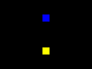
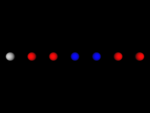
Here's a VRML 2.0 file that specifies two points.
Just like in the previous example, we had to use a Shape node
and place PointSet node in it's geometry
field. PointSet node, in turn, has two more
SFNode fields: coord
(that can contain Coordinate node)
and color (that can contain Color node).
Coordinate node has a point field
of type MFVec3f — these are positions
of defined points. Color node has a
color field of type MFColor —
these are colors of points, specified in the same order as in
the Coordinate node.
Note that PointSet and Color
nodes have the same field name: color.
In the first case, this is an SFNode field,
in the second case it's an MFVec3f field.
#VRML V2.0 utf8

Shape {
  geometry PointSet {
    coord Coordinate { point [ 0 -2 0, 0 2 0 ] }
    color Color { color [ 1 1 0, 0 0 1 ] }
  }
}
Now we're approaching the fundamental idea of VRML: some
nodes can be placed as a children of other nodes. We already
saw some examples of this idea in VRML 2.0 examples
above: we placed various nodes inside geometry
field of Shape node. VRML 1.0 has a little different
way of specifying children nodes (inherited from Inventor format)
than VRML 2.0 and X3D — we will see both methods.
In VRML 1.0, you just place children nodes inside the parent node. Like this:
#VRML V1.0 ascii

Group {
  Sphere { }
  Cube { width 1.5 height 1.5 depth 1.5 }
}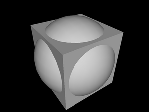
Group is the simplest grouping node.
It has no fields, and it's only purpose is just to treat a couple of nodes
as one node.
Note that in VRML 1.0 it's required that a whole VRML file consists of exactly one root node, so we actually had to use some grouping node here. For example the following file is invalid according to VRML 1.0 specification:
#VRML V1.0 ascii

Sphere { }
Cube { width 1.5 height 1.5 depth 1.5 }
Nevertheless the above example is handled by many VRML engines, including our engine described in this document.
In VRML 2.0, you don't place children nodes directly
inside the parent node. Instead you place children nodes inside
fields of type SFNode (this contains
zero (NULL) or one node) or
MFNode (this contains any number (possibly zero)
of nodes). For example, in VRML 2.0 Group
node has an MFNode field children,
so the example file in VRML 2.0 equivalent to previous example looks like
this:
#VRML V2.0 utf8

Group {
  children [
    Shape { geometry Sphere { } }
    Shape { geometry Box { size 1.5 1.5 1.5 } }
  ]
}
Syntax of MFNode is just like for other multiple-valued
fields: a sequence of values, inside brackets ([
and ]).
Example above also shows a couple of other differences between VRML 1.0 and 2.0:
In VRML 2.0 we have to wrap
SphereandBoxnodes inside aShapenode.Node
Cubefrom VRML 1.0 was renamed toBoxin VRML 2.0.Size of the box in VRML 2.0 is specified using
sizefield of typeSFVec3f, while in VRML 1.0 we had three fields (width,height,depth) of typeSFFloat.
While we're talking about VRML versions differences, note also that
in VRML 2.0 a file can have any number of root nodes. So actually
we didn't have to use Group node in our example,
and the following would be correct VRML 2.0 file too:
#VRML V2.0 utf8

Shape { geometry Sphere { } }
Shape { geometry Box { size 1.5 1.5 1.5 } }
To be honest, we have to point one more VRML difference: as was mentioned before, in VRML 2.0 shapes are unlit by default. So our VRML 2.0 examples above look like this:
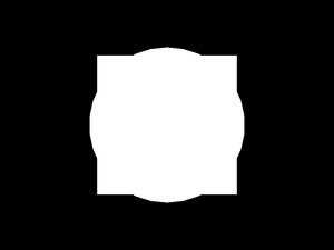
To make them lit, we must assign a material
for them. In VRML 2.0 you do this by placing a Material
node inside material field of Appearance
node. Then you place Appearance node inside
appearance field of
appropriate Shape node. Result looks like this:
#VRML V2.0 utf8

Group {
  children [
    Shape {
      appearance Appearance { material Material { } }
      geometry Sphere { }
    }
    Shape {
      appearance Appearance { material Material { } }
      geometry Box { size 1.5 1.5 1.5 }
    }
  ]
}
We didn't specify any Material node's fields,
so the default properties will be used. Default VRML 2.0 material properties
are the same as for VRML 1.0: light gray diffuse color and a slight
ambient color.
As you can see, VRML 2.0 description gets significantly more verbose than VRML 1.0, but it has many advantages:
The way how children nodes are specified in VRML 2.0 requires you to always write an
SFNodeorMFNodefield name (as opposed to VRML 1.0 where you just write the children nodes). But the advantages are obvious: in VRML 2.0 you can explicitly assign different meaning to different children nodes by placing them within different fields. In VRML 1.0 all the children nodes had to be treated in the same manner — the only thing that differentiated children nodes was their position within the parent.As mentioned earlier, the default behavior of various VRML 2.0 parts is the one that is the easiest to render. That's why the default behavior is to render unlit, and you have to explicitly specify material to get lit objects.
This is a good thing, since it makes VRML authors more conscious about using features, and hopefully it will force them to create VRML worlds that are easier to render. In the case of rendering unlit objects, this is often perfectly acceptable (or even desired) solution if the object has a detailed texture applied.
Placing the
Materialnode inside theSFNodefield ofAppearance, and then placing theAppearancenode inside theSFNodefield ofShapemay seem like a “bondage-and-discipline language”, but it allows various future enhancements of the language without breaking compatibility. For example you could invent a node that allows to specify materials using a different properties (like by describing it's BRDF function, useful for rendering realistic images) and then just allow this node as a value for thematerialfield.Scenario described above actually happened. First versions of VRML 97 specification didn't include geospatial coordinates support, including a node
GeoCoordinate. A nodeIndexedFaceSethas a fieldcoordused to specify a set of points for geometry, and initially you could place aCoordinatenode there. When specification of geospatial coordinates support was formulated (and added to VRML 97 specification as optional for VRML browsers), all that had to be changed was to say that now you can placeGeoCoordinateeverywhere where earlier you could use onlyCoordinate.The
Shapenode in VRML 2.0 contains almost whole information needed to render given shape. This means that it's easier to create a VRML rendering engine. We will contrast this with VRML 1.0 approach that requires a lot of state information in Section 1.5, “VRML 1.0 state”.
Let's take a look at another grouping node:
VRML 2.0 Transform
node. This node specifies a transformation (a mix
of a translation, a rotation and a scale) for all it's children nodes.
The default field values are such that no transformation actually
takes place, because by default we translate by (0, 0, 0) vector,
rotate by zero angle and scale by 1.0 factor. This means that
the Transform node with all fields left as default
is actually equivalent to a Group node.
Example of a simple translation:
#VRML V2.0 utf8

Shape {
  appearance Appearance { material Material { } }
  geometry Box { }
}

Transform {
  translation 5 0 0
  children Shape {
    appearance Appearance { material Material { } }
    geometry Sphere { }
  }
}
Note that a child of a Transform node
may be another Transform node. All transformations
are accumulated. For example these two files are equivalent:
#VRML V2.0 utf8

Shape {
  appearance Appearance { material Material { } }
  geometry Box { }
}

Transform {
  translation 5 0 0
  children [
    Shape {
      appearance Appearance { material Material { } }
      geometry Sphere { }
    }

    Transform {
      translation 5 0 0
      scale 1 3 1
      children Shape {
        appearance Appearance { material Material { } }
        geometry Sphere { }
      }
    }
  ]
}
#VRML V2.0 utf8
Shape {
appearance Appearance { material Material { } }
geometry Box { }
}
Transform {
translation 5 0 0
children Shape {
appearance Appearance { material Material { } }
geometry Sphere { }
}
}
Transform {
translation 10 0 0
scale 1 3 1
children Shape {
appearance Appearance { material Material { } }
geometry Sphere { }
}
}
A
Switchnode allows you to choose only one (or none) from children nodes to be in the active (i.e. visible, participating in collision detection etc.) part of the scene. This is useful for various scripts and it's also useful for hiding nodes referenced later — we will see an example of this in Section 1.4, “DEF / USE mechanism”.A
Separatorand aTransformSeparatornodes in VRML 1.0. We will see what they do in Section 1.5, “VRML 1.0 state”.A
LODnode (the name is an acronym for level of detail) specifies a different versions of the same object. The intention is that all children nodes represent the same object, but with different level of detail: first node is the most detailed one (and difficult to render, check for collisions etc.), second one is less detailed, and so on, until the last node has the least details (it can even be empty, which can be expressed by aGroupnode with no children). VRML browser should choose the appropriate children to render based on the distance between the viewer and designated center point.A
Collisionnode is available in VRML 2.0 and X3D. It's very useful to disable collisions for particular shapes (visible but not collidable geometry), or to specify a “proxy” shape to be used for collisions. “Proxy” can be used to perform collisions with a complicated 3D object by a simpler shape, for example a complicated statue of a human could be surrounded by a simple box proxy for the sake of collisions. Also, this can be used to make collidable but invisible geometry.
VRML nodes may be named and later referenced. This allows
you to reuse the same node (which can be any VRML node type —
like a shape, a material, or even a whole group) more than once. The syntax
is simple: you name a node by writing
DEF <node-name> before node type.
To reuse the node, just write USE <node-name>.
This mechanism is available in all VRML versions.
Here's a simple example
that uses the same Cone
twice, each time with a different material color.
#VRML V2.0 utf8

Shape {
  appearance Appearance {
    material Material { diffuseColor 1 1 0 }
  }
  geometry DEF NamedCone Cone { height 5 }
}

Transform {
  translation 5 0 0
  children Shape {
    appearance Appearance {
      material Material { diffuseColor 0 0 1 } }
    geometry USE NamedCone
  }
}
Using DEF / USE mechanism makes your VRML files
smaller and easier to author, and it also allows
VRML implementations to save resources (memory, loading time...).
That's because VRML implementation can allocate the node
once, and then just copy the pointer to this node.
VRML specifications are formulated to make this
approach always correct, even when mixed with features like
scripting or sensors. Note that some nodes
can “pull” additional data with them
(for example ImageTexture nodes will load
texture image from file), so the memory saving may be even larger.
Consider these two VRML files:
#VRML V2.0 utf8

Shape {
  appearance Appearance {
    texture DEF SampleTexture
      ImageTexture { url "../textures/test_texture.png" }
  }
  geometry Box { }
}

Transform {
  translation 5 0 0
  children Shape {
    appearance Appearance {
      texture USE SampleTexture
    }
    geometry Sphere { }
  }
}
#VRML V2.0 utf8
Shape {
appearance Appearance {
texture ImageTexture { url "../textures/test_texture.png" }
}
geometry Box { }
}
Transform {
translation 5 0 0
children Shape {
appearance Appearance {
texture ImageTexture { url "../textures/test_texture.png" }
}
geometry Sphere { }
}
}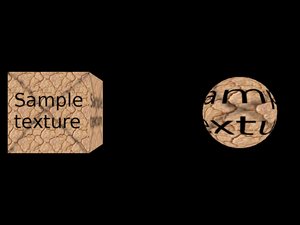
Both files above look the same when rendered, but in the first case VRML implementation loads the texture only once, since we know that this is the same texture node [3].
Note that the first node definition, with DEF
keyword, not only names the node, but also includes it in the file.
Often it's more comfortable to first define a couple of named
nodes (without actually using them) and then use them.
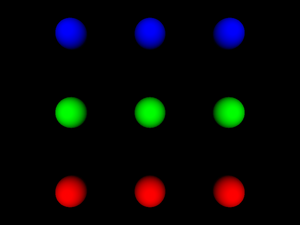
You can use the Switch node for this
— by default Switch node doesn't
include any of it's children nodes, so you can write
VRML file like this:
#VRML V2.0 utf8

Switch {
  choice [
    DEF RedSphere Shape {
      appearance Appearance {
        material Material { diffuseColor 1 0 0 } }
      geometry Sphere { }
    }
    DEF GreenSphere Shape {
      appearance Appearance {
        material Material { diffuseColor 0 1 0 } }
      geometry Sphere { }
    }
    DEF BlueSphere Shape {
      appearance Appearance {
        material Material { diffuseColor 0 0 1 } }
      geometry Sphere { }
    }
    DEF SphereColumn Group {
      children [
        Transform { translation 0 -5 0 children USE RedSphere }
        Transform { translation 0  0 0 children USE GreenSphere }
        Transform { translation 0  5 0 children USE BlueSphere }
      ]
    }
  ]
}

Transform { translation -5 0 0 children USE SphereColumn }
Transform { translation  0 0 0 children USE SphereColumn }
Transform { translation  5 0 0 children USE SphereColumn }
One last example shows a reuse of Coordinate
node. Remember that a couple of sections earlier we defined
a simple PointSet. PointSet
node has an SFNode field named coord.
You can place there a Coordinate node.
A Coordinate node, in turn, has a point
field of type SFVec3f that allows you to specify
point positions. The obvious question is “Why all this complexity?
Why not just say that coord field is
of SFVec3f type and directly include the point
positions?”. One answer was given earlier when talking
about grouping nodes: this allowed VRML specification for painless
addition of GeoCoordinate as an alternative
way to specify positions. Another answer is given by the example
below. As you can see, the same set of positions may be used
by a couple of different nodes[4].
#VRML V2.0 utf8

Shape {
  appearance Appearance { material Material { } }
  geometry IndexedFaceSet {
    coord DEF TowerCoordinates Coordinate {
      point [
        4.157832 4.157833 -1.000000,
        4.889094 3.266788 -1.000000,
        ......
      ]
    }

    coordIndex [
      63 0 31 32 -1,
      31 30 33 32 -1,
      ......
    ]
  }
}

Transform {
  translation 30 0 0
  children Shape {
    geometry IndexedLineSet {
      coordIndex [
        63 0 31 32 63 -1,
        31 30 33 32 31 -1,
        ......
      ]
      coord USE TowerCoordinates
    }
  }
}

Transform {
  translation 60 0 0
  children Shape {
    geometry PointSet {
      coord USE TowerCoordinates
    }
  }
}
Now that we know all about children relationships and DEF / USE mechanism, we can grasp the statement mentioned at the beginning of this chapter: every VRML file is a directed graph of nodes. It doesn't have cycles, although if we will forget about direction of edges (treat it as an undirected graph), we can get cycles (because of DEF / USE mechanism).
Note that VRML 1.0 file must contain exactly one root node,
while VRML 2.0 file is a sequence of any number of root nodes.
So, being precise, VRML graph doesn't have to be a connected graph.
But actually our engine when reading VRML file with many
root nodes just wraps them in an “invisible”
Group node. This special Group
node acts just like any other group node, but it's not written
back to the file (when e.g. using our engine to pretty-print VRML files).
This way, internally, we always see VRML file as a connected graph,
with exactly one root node.
In previous sections most of the examples were given only in VRML 2.0 version. Partially that's because VRML 2.0 is just newer and better, so you should use it instead of VRML 1.0 whenever possible. But partially that was because we avoided to explain one important behavior of VRML 1.0. In this section we'll fill the gap. Even if you're not interested in VRML 1.0 anymore, this information may help you understand why VRML 2.0 was designed the way it was, and why it's actually better than VRML 1.0. That's because part of the reasons of VRML 2.0 changes were to avoid the whole issue described here.
Historically, VRML 1.0 was based on Inventor file format,
and Inventor file format was
designed specifically with OpenGL implementation in mind.
Those of you who do any programming in OpenGL know that OpenGL
works as a state machine. This means
that OpenGL remembers a lot of “global” settings
[5]. When you want to render
a vertex (aka point) in OpenGL, you just call one simple command
(glVertex), passing only point coordinates.
And the vertex is rendered (along with a line or even a triangle
that it produces with other vertexes). What color does the vertex
has? The last color specified by glColor
call (or glMaterial, mixed with lights).
What texture coordinate does it have? Last texture coordinate
specified in glTexCoord call. What texture
does it use? Last texture bound with glBindTexture.
We can see a pattern here: when you want to know what property
our vertex has, you just have to check what value we last assigned
to this property. When we talk about OpenGL state, we talk
about all the “last glColor”,
“last glTexCoord” etc. values
that OpenGL has to remember.
Inventor, and then VRML 1.0, followed a similar approach.
“What material does a sphere use?” The one specified in the last
Material node. Take a look at the example:
#VRML V1.0 ascii

Group {
  # Default material will be used here:
  Sphere { }

  DEF RedMaterial Material { diffuseColor 1 0 0 }

  Transform { translation 5 0 0 }
  # This uses the last material : red
  Sphere { }

  Transform { translation 5 0 0 }
  # This still uses uses the red material
  Sphere { }

  Material { diffuseColor 0 0 1 }

  Transform { translation 5 0 0 }
  # Material changed to blue
  Sphere { }

  Transform { translation 5 0 0 }
  # Still blue...
  Sphere { }

  USE RedMaterial

  Transform { translation 5 0 0 }
  # Red again !
  Sphere { }

  Transform { translation 5 0 0 }
  # Still red.
  Sphere { }
}
Similar answers are given for other questions in the form “What is used?”. Let's compare VRML 1.0 and 2.0 answers for such questions:
What texture is used?
VRML 1.0 answer: Last
Texture2node.VRML 2.0 answer: Node specified in enclosing
Shapeappearance'stexturefield.What coordinates are used by
IndexedFaceSet?VRML 1.0 answer: Last
Coordinate3node.VRML 2.0 answer: Node specified in
coordfield of givenIndexedFaceSet.What font is used by by
AsciiTextnode (renamed to justTextin VRML 2.0)?VRML 1.0 answer: Last
FontStylenode.VRML 2.0 answer: Node specified in
fontStylefield of givenTextnode.
So VRML 1.0 approach maps easily to OpenGL.
Simple VRML implementation can just traverse the scene graph,
and for each node do appropriate set of OpenGL calls.
For example, Material node will correspond
to a couple of glMaterial and glColor
calls. Texture2 will correspond to binding
prepared OpenGL texture. Visible geometry nodes will cause
rendering of appropriate geometry, and so last
Material and Texture2
settings will be used.
In our example with materials above you can also
see another difference between VRML 1.0 and 2.0,
also influenced by the way things are done in OpenGL:
the way Transform node is used.
In VRML 2.0, Transform affected it's children.
In VRML 1.0, Transform node is not supposed to
have any children. Instead, it affects all subsequent nodes.
If we would like to translate last example to VRML 2.0,
each Transform node would have to be placed
as a last child of previous Transform node,
thus creating a deep nodes hierarchy. Alternatively, we could
keep the hierarchy shallow and just use
Transform { translation 5 0 0 ... }
for the first time, then Transform { translation 10 0 0 ... },
then Transform { translation 15 0 0 ... } and so on.
This means that simple VRML 1.0 implementation will just call
appropriate matrix transformations when processing Transform
node. In VRML 1.0 there are even more specialized
transformation nodes. For example a node Translation
that has a subset of features of full Transform node:
it can only translate. Such Translation
has an excellent, trivial mapping to OpenGL: just call
glTranslate.
There's one more important feature of OpenGL
“state machine” approach: stacks. OpenGL has a matrix
stack (actually, three matrix stacks for each matrix type) and
an attributes stack. As you can guess, there are nodes in VRML 1.0
that, when implemented in an easy way, map perfectly
to OpenGL push/pop stack operations: Separator
and TransformSeparator. When you use
Group node in VRML 1.0, the properties
(like last used Material and Texture2,
and also current transformation and texture transformation)
“leak” outside of Group node,
to all subsequent nodes.
But when you use Separator,
they do not leak out: all transformations and “who's the last
material/texture node” properties are unchanged
after we leave Separator node.
So simple Separator implementation in OpenGL
is trivial:
At the beginning, use
glPushAttrib(saving all OpenGL attributes that can be changed by VRML nodes) andglPushMatrix(for both modelview and texture matrices).Then process all children nodes of
Separator.Then restore state by
glPopAttribandglPopMatrixcalls.
TransformSeparator is a cross between
a Separator and a Group:
it saves only transformation matrix, and the rest of the state
can “leak out”. So to implement this in OpenGL,
you just call glPushMatrix (on modelview matrix)
before processing children and glPopMatrix
after.
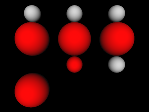
Below is an example how various VRML 1.0 grouping nodes allow
“leaking”. Each column starts with a standard
Sphere node. Then we enter some
grouping node (from the left: Group,
TransformSeparator and Separator).
Inside the grouping node we change material, apply scaling transformation
and put another Sphere node — middle
row always contains a red large sphere. Then we exit
from grouping node and put the third Sphere node.
How does this sphere look like depends on used grouping node.
#VRML V1.0 ascii

Separator {
  Sphere { }
  Transform { translation 0 -3 0 }
  Group {
    Material { diffuseColor 1 0 0 }
    Transform { scaleFactor 2 2 2 }
    Sphere { }
  }
  # A Group, so both Material change and scaling "leaks out"
  Transform { translation 0 -3 0 }
  Sphere { }
}

Transform { translation 5 0 0 }

Separator {
  Sphere { }
  Transform { translation 0 -3 0 }
  TransformSeparator {
    Material { diffuseColor 1 0 0 }
    Transform { scaleFactor 2 2 2 }
    Sphere { }
  }
  # A TransformSeparator, so only Material change "leaks out"
  Transform { translation 0 -3 0 }
  Sphere { }
}

Transform { translation 5 0 0 }

Separator {
  Sphere { }
  Transform { translation 0 -3 0 }
  Separator {
    Material { diffuseColor 1 0 0 }
    Transform { scaleFactor 2 2 2 }
    Sphere { }
  }
  # A Separator, so nothing "leaks out".
  # The last sphere is identical to the first one.
  Transform { translation 0 -3 0 }
  Sphere { }
}
There are some advantages of VRML 1.0 “state” approach:
It maps easily to OpenGL.
Such easy mapping may be also quite efficient. For example, if two nodes use the same
Materialnode, we can just change OpenGL material once (at the timeMaterialnode is processed). VRML 2.0 implementation must remember last setMaterialnode to achieve this purpose.It's flexible. The way transformations are specified in VRML 2.0 forces us often to create deeper node hierarchies than in VRML 1.0.
And in VRML 1.0 we can easier share materials, textures, font styles and other properties among a couple of nodes. In VRML 2.0 such reusing requires naming nodes by DEF / USE mechanism. In VRML 1.0 we can simply let a couple of nodes have the same node as their last
Material(or similar) node.
But there are also serious problems with VRML 1.0 approach, that VRML 2.0 solves.
The argumentation about “flexibility” of VRML 1.0 above looks similar to argumentation about various programming languages (...programming languages that should remain nameless here...), that are indeed flexible but also allow the programmer to “shoot himself in the foot”. It's easy to forget that you changed some material or texture, and accidentally affect more than you wanted.
Compare this with the luxury of VRML 2.0 author: whenever you start writing a
Shapenode, you always start with a clean state: if you don't specify a texture, shape will not be textured, if you don't specify a material, shape will be unlit, and so on. If you want to know how givenIndexedFaceSetwill look like when rendered, you just have to know it's enclosingShapenode. More precisely, the only things that you have to know for VRML 2.0 node to render it areenclosing
Shapenode,accumulated transformation from
Transformnodes,and some “global” properties: lights that affect this shape and fog properties. I call them “global” because usually they are applied to the whole scene or at least large part of it.
On the other hand, VRML 1.0 author or reader (human or program) must carefully analyze the code before given node, looking for last
Materialnode occurrence etc.The argumentation about “simple VRML 1.0 implementation” misses the point that such simple implementation will in fact suffer from a couple of problems. And fixing these problems will in fact force this implementation to switch to non-trivial methods. The problems include:
OpenGL stacks sizes are limited, so a simple implementation will limit allowed depth of
SeparatorandTransformSeparatornodes.If we will change OpenGL state each time we process a state-changing node, then we can waste a lot of time and resources if actually there are no shapes using given property. For example this code
Separator {
  Texture2 { filename "texture.png" }
}
will trick a naive implementation into loading from file and then loading to OpenGL context a completely useless texture data.
This seems like an irrelevant problem, but it will become a large problem as soon as we will try to use any technique that will have to render only parts of the scene. For example, implementing material transparency using OpenGL blending requires that first all non-transparent shapes are rendered. Also implementing culling of objects to a camera frustum will make many shapes in the scene ignored in some frames.
Last but not least: in VRML 1.0, grouping nodes must process their children in order, to collect appropriate state information needed to render each geometry. In VRML 2.0, there is no such requirement. For example, to render a
Groupnode in VRML 2.0, implementation can process and render children nodes in any order. Like said above, VRML 2.0 must only know about current transformation and global things like fog and lights. The rest of information needed is always contained within appropriateShapenode.VRML 2.0 implementation can even ignore some children in
Groupnode if it's known that they are not visible.Example situations when implementation should be able to freely choose which shapes (and in what order) are rendered were given above: implementing transparency using blending, and culling to camera frustum.
More about the way how we solved this problem for both VRML 1.0 and 2.0 in Section 3.10, “VRML scene”. More about OpenGL blending and culling to frustum in Section 6.4, “VRML scene class for OpenGL”.
Now that we're accustomed with VRML syntax and concepts, let's take a quick look at some notable VRML features that weren't shown yet.
A powerful tool of VRML is the ability to include one
model as a part of another. In VRML 2.0 we do this by
Inline node. It's url
field specifies the URL (possibly relative) of VRML file to load.
Note that our engine doesn't actually support URLs right now
and treats this just as a file name.
The content of referenced VRML file is placed at the position
of given Inline node. This means that you
can apply transformation to inlined content. This also
means that including the same file more than once is sensible
in some situations. But remember the remarks in Section 1.4, “DEF / USE mechanism”:
if you want to include the same file more than once, you should
name the Inline node and then just reuse it.
Such reuse will conserve resources.
url field is actually MFString
and is a sequence of URL values, from the most to least preferred one.
So VRML browser will try to load files from given URLs in order,
until a valid file will be found.
In VRML 1.0 the node is called WWWInline,
and the URL (only one is allowed, it's SFString
field) is specified in the field name.
When using our engine you can mix VRML/X3D versions and include VRML 1.0 file from VRML 2.0, or X3D, or the other way around. Moreover, you can include other 3D formats (like 3DS and Wavefront OBJ) too.
#VRML V2.0 utf8

DEF MyInline Inline { url "reuse_cone.wrl" }

Transform {
  translation 1 0 0
  rotation 1 0 0 -0.2
  children [
    USE MyInline

Transform {
  translation 1 0 0
  rotation 1 0 0 -0.2
  children [
    USE MyInline

Transform {
  translation 1 0 0
  rotation 1 0 0 -0.2
  children [
    USE MyInline

Transform {
  translation 1 0 0
  rotation 1 0 0 -0.2
  children [
    USE MyInline

] } ] } ] } ] }
Figure 1.15. Our earlier example of reusing cone inlined a couple of times, each time with a slight translation and rotation
VRML allows you to specify a texture coordinate transformation. This allows you to translate, scale and rotate visible texture on given shape.
In VRML 1.0, you do this by Texture2Transform
node — this works analogous to Transform,
but transformations are only 2D. Texture transformations in VRML 1.0
accumulate, just like normal transformations. Here's an example:
#VRML V1.0 ascii

Group {
  Texture2 { filename "../textures/test_texture.png" }

  Cube { }

  Transform { translation 3 0 0 }

  Separator {
    # translate texture
    Texture2Transform { translation 0.5 0.5 }
    Cube { }
  }

  Transform { translation 3 0 0 }

  Separator {
    # rotate texture by Pi/4
    Texture2Transform { rotation 0.7853981634 }
    Cube { }
  }

  Transform { translation 3 0 0 }

  Separator {
    # scale texture
    Texture2Transform { scaleFactor 2 2 }
    Cube { }

    Transform { translation 3 0 0 }

    # rotate texture by Pi/4.
    # Texture transformation accumulates, so this will
    # be both scaled and rotated.
    Texture2Transform { rotation 0.7853981634 }
    Cube { }
  }
}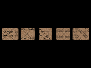
Remember that we transform texture coordinates, so e.g. scale 2x means that the texture appears 2 times smaller.
VRML 2.0 proposes a different approach here:
We have similar TextureTransform node, but we can
use it only as a value for textureTransform field
of Appearance. This also means that there
is no way how texture transformations could accumulate.
Here's a VRML 2.0 file equivalent to previous VRML 1.0 example:
#VRML V2.0 utf8

Shape {
  appearance Appearance {
    texture DEF SampleTexture
      ImageTexture { url "../textures/test_texture.png" }
  }
  geometry Box { }
}

Transform {
  translation 3 0 0
  children Shape {
    appearance Appearance {
      texture USE SampleTexture
      # translate texture
      textureTransform TextureTransform { translation 0.5 0.5 }
    }
    geometry Box { }
  }
}

Transform {
  translation 6 0 0
  children Shape {
    appearance Appearance {
      texture USE SampleTexture
      # rotate texture by Pi/4
      textureTransform TextureTransform { rotation 0.7853981634 }
    }
    geometry Box { }
  }
}

Transform {
  translation 9 0 0
  children Shape {
    appearance Appearance {
      texture USE SampleTexture
      # scale texture
      textureTransform TextureTransform { scale 2 2 }
    }
    geometry Box { }
  }
}

Transform {
  translation 12 0 0
  children Shape {
    appearance Appearance {
      texture USE SampleTexture
      # scale and rotate the texture.
      # There's no way to accumulate texture transformations,
      # so we just do both rotation and scaling by
      # TextureTransform node below.
      textureTransform TextureTransform {
        rotation 0.7853981634
        scale 2 2
      }
    }
    geometry Box { }
  }
}
You can specify various navigation information using
the NavigationInfo node.
typefield describes preferred navigation type. You can “EXAMINE” model, “WALK” in the model (with collision detection and gravity) and “FLY” (collision detection, but no gravity).avatarSizefield sets viewer (avatar) sizes. These typically have to be adjusted for each world to “feel right”. Although you should note that VRML generally suggests to treat length 1.0 in your world as “1 meter”. If you will design your VRML world following this assumption, then defaultavatarSizewill feel quite adequate, assuming that you want the viewer to have human size in your world. Viewer sizes are used for collision detection.Viewer size together with
visibilityLimitmay be also used to set VRML browsers Z-buffer near and far clipping planes. This is the case with our engine. By default our engine tries to calculate sensible values for near and far based on scene bounding box size.You can also specify moving speed (
speedfield), and whether head light is on (headlightfield).
To specify default viewer position and orientation in the
world you use Viewpoint node. In VRML 1.0,
instead of Viewpoint you have
PerspectiveCamera and
OrthogonalCamera (in VRML 2.0 viewpoint
is always perspective). Viewpoint and camera nodes may be generally
specified anywhere in the file. The first viewpoint/camera node
found in the file (but only in the active part of the file —
e.g. not in inactive children of Switch)
will be used as the starting position/orientation.
Note that viewpoint/camera nodes
are also affected by transformation.
Finally, note that my VRML viewer view3dscene has a useful function to print VRML viewpoint/camera nodes ready to be pasted to VRML file, see menu item “Console” -> “Print current camera node”.
Here's an example file. It defines a viewpoint (generated
by view3dscene) and a navigation info
and then includes actual world geometry from other file
(shown in our earlier example
about inlining).
#VRML V2.0 utf8

Viewpoint  {
  position 11.832 2.897 6.162
  orientation -0.463 0.868 0.172 0.810
}

NavigationInfo {
  avatarSize [ 0.5, 2 ]
  speed 1.0
  headlight TRUE
}

Inline { url "inline.wrl" }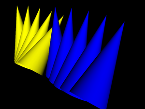
IndexedFaceSet nodes (and a couple of other
nodes in VRML 2.0 like ElevationGrid) have
some notable features to make their rendering better and
more efficient:
You can use non-convex faces if you set
convexfield toFALSE. It will be VRML browser's responsibility to correctly triangulate them. By default faces are assumed to be convex (following the general rule that the default behavior is the easiest one to handle by VRML browsers).By default shapes are assumed to be
solidwhich allows to use backface culling when rendering them.If you don't supply pre-generated normal vectors for your shapes, they will be calculated by the VRML browser. You can control how they will be calculated by the
creaseAnglefield: if the angle between adjacent faces will be less than specifiedcreaseAngle, the normal vectors in appropriate points will be smooth. This allows you to specify preferred “smoothness” of the shape. In VRML 2.0 by defaultcreaseAngleis zero (so all normals are flat; again this follows the rule that the default behavior is the easiest one for VRML browsers). See example below.For VRML 1.0 the
creaseAngle, backface culling and convex faces settings are controlled byShapeHintsnode.All VRML shapes have some sensible default texture mapping. This means that you don't have to specify texture coordinates if you want the texture mapped. You only have to specify some texture. For
IndexedFaceSetthe default texture mapping adjusts to shape's bounding box (see VRML specification for details).
Here's an example of the creaseAngle
use. Three times we define the same geometry in IndexedFaceSet
node, each time using different creaseAngle values.
The left tower uses creaseAngle 0, so all
faces are rendered flat. Second tower uses creaseAngle 1
and it looks good — smooth where it should be.
The third tower uses creaseAngle 4,
which just means that normals are smoothed everywhere (this case
is actually optimized inside our engine, so it's calculated
faster) — it looks bad, we can see that normals are
smoothed where they shouldn't be.
#VRML V2.0 utf8

Viewpoint  {
  position 31.893 -69.771 89.662
  orientation 0.999 0.022 -0.012 0.974
}

Transform {
  children Shape {
    appearance Appearance { material Material { } }
    geometry IndexedFaceSet {
      coord DEF TowerCoordinates Coordinate {
        point [
          4.157832 4.157833 -1.000000,
          4.889094 3.266788 -1.000000,
          ......
        ]
      }

      coordIndex [
        63 0 31 32 -1,
        31 30 33 32 -1,
        ......
      ]
      creaseAngle 0
    }
  }
}

Transform {
  translation 30 0 0
  children Shape {
    appearance Appearance { material Material { } }
    geometry IndexedFaceSet {
      coordIndex [
        63 0 31 32 -1,
        31 30 33 32 -1,
        ......
      ]
      coord USE TowerCoordinates
      creaseAngle 1
    }
  }
}

Transform {
  translation 60 0 0
  children Shape {
    appearance Appearance { material Material { } }
    geometry IndexedFaceSet {
      coordIndex [
        63 0 31 32 -1,
        31 30 33 32 -1,
        ......
      ]
      coord USE TowerCoordinates
      creaseAngle 4
    }
  }
}
- Prototypes
These constructions define new VRML nodes in terms of already available ones. The idea is basically like macros, but it works on VRML nodes level (not on textual level, even not on VRML tokens level) so it's really safe.
- External prototypes
These constructions define syntax of new VRML nodes, without defining their implementation. The implementation can be specified in other VRML file (using normal prototypes mentioned above) or can be deduced by particular VRML browser using some browser-specific means (for example, a browser may just have some non-standard nodes built-in). If a browser doesn't know how to handle given node, it can at least correctly parse the node (and ignore it).
For example, many VRML browsers handle some non-standard VRML nodes. If you use these nodes and you want to make your VRML files at least readable by other VRML browsers, you should declare these non-standard nodes using external prototypes.
Even better, you can provide a list of proposed implementations for each external prototype. They are checked in order, VRML browser should chose the first implementation that it can use. So you can make the 1st item a URN that is recognized only by your VRML browser, and indicating built-in node implementation. And the 2nd item may point to a URL with another VRML file that at least partially emulates the functionality of this non-standard node, by using normal prototype. This way other VRML browsers will be able to at least partially make use of your node.
Our engine handles prototypes and external prototypes perfectly
(since around September 2007). We have some VRML/X3D extensions
(see
Castle Game Engine extensions list),
and they can be declared as external prototypes
with URN like
"urn:castle-engine.sourceforge.net:node:KambiOctreeProperties".
So other VRML browsers should be able to at least parse them.
X3D is a direct successor to VRML 2.0. X3D header even openly
specifies #X3D V3.0 utf8 (or 3.1,
or 3.2) admitting that it's just a 3rd version
of VRML.
X3D is almost absolutely compatible with VRML 2.0, meaning
that almost all VRML 2.0 files are also correct X3D files —
assuming that we change the header to indicate X3D and add trivial
PROFILE line.
Minor incompatible changes include renaming of access specifiers
(exposedField becomes inputOutput,
eventIn becomes inputOnly etc.),
and changes to some field names (Switch.choice and
LOD.level were renamed to Switch.children
and LOD.children, this made the “containerField” mechanism
of X3D XML encoding more useful). There was no revolutionary compatibility
break on the road to X3D, and everything that we said in this chapter
about VRML 2.0 applied also to X3D.
Some of the improvements of X3D:
- Encodings
VRML classic encoding is for compatibility with VRML 2.0.
XML encoding allows to validate and process X3D files with XML tools (like XML Schema, XSLT). It also allows easier implementation, since most programming languages include XML reading/writing support (usually using the DOM API). So you don't have to write lexer and parser (like for classic VRML).
Finally, binary encoding (not implemented in our engine yet) allows smaller files and makes parsing faster.
There is no requirement to support all three encodings in every X3D browser — you only have to support one. XML encoding is the most popular and probably the simpler to implement, so this is the suggested choice. All encodings are completely interchangeable, which means that we can convert X3D files back and forth from any encoding to any other, and no information is lost. Many tools exist to convert from one encoding to the other (our own engine can be used to convert between XML and classic encoding, see https://castle-engine.io/view3dscene.php#section_converting).
- Components and profiles
VRML 2.0 standard was already quite large, and implementing full VRML 2.0 browser was a difficult and long task. At the same time, pretty much everyone who used VRML for more advanced tasks wanted to extend it in some way. So it seemed that the standard was large, and it had to grow even larger... clearly, there was a problem.
The first part of the solution in X3D is to break the standard into many small components. Component is just a part of the specification dealing with particular functionality. The crucial part of each component are it's nodes, and some specification how these nodes cooperate with the rest of the scene. For example, there is a component with 2D geometry, called
Geometry2D. There is a component providing high-level shaders (GLSL, HLSL, Cg) support calledShaders. Currently (as of X3D edition 2) there are 34 components defined by the specification. Every node is part of some component. Naturally, some components depend on other components.Some components are complicated enough to be divided even more — into levels. For example, implementing component on lower level may mean that some node is only optionally supported, or maybe some of it's fields may be ignored, or maybe there may exist some limits on the data. For example, for the
Networkingcomponent, level 1 means that program must support only local (file://) absolute URLs. For level 2, additionallyhttp://must be supported, and URLs may be relative. On level 4 securehttps://must be additionally supported.The author of X3D file can request, at the beginning of X3D file, which components and on what levels must be supported to handle this file. For example, in classic VRML encoding lines
COMPONENT Networking:2
COMPONENT NURBS:1
mean that networking component must be support relative and and absolute
http://andfile://URLs and basic NURBS support is required.Now, the components and levels only divide the standard into small parts. It would be a nightmare to specify at the beginning of each file all required components. It would also do no good to compatibility across X3D browsers: if every browser would be allowed to support any set of any components, we would have no guarantee that even the most basic X3D file is supported by reasonable X3D browsers. So the second part of the solution are profiles. Profile is basically a set of components and their levels, and some additional conditions. There are only few profiles (six, as of X3D edition 2), like
Core,Interchange,InteractiveandFull. The idea is that when browser claims “I support Interchange profile”, then we already know quite a lot about what it supports (Interchange includes most of the static 3D data), and what it possibly doesn't support (interaction, like non-trivial sensors, is not included in the Interchange profile).Each X3D file must state at the beginning which profile it requires to operate. For example, in classic VRML encoding, the
PROFILEline is required, likePROFILE Interchange
Summing it up, the X3D author specifies first the profile and then optionally any number of components (and their levels) which must be supported (in addition to features already requested by the profile). Effectively, X3D browsers can support any components at any level, but they are also strongly pushed to support some high profile. X3D authors can request any profile and components combination they want, and are relatively safe to expect support from most browsers for Interchange or even Interactive profiles.
- New graphic features
As said, there are 34 X3D components, surely there are many new interesting nodes, far too many to actually list them here. You can take a quick look at the X3D specification table of contents at this point.
OK, some of the more interesting additions (not present in VRML 97 amendment 1), in my opinion: humanoid animation (H-Anim), programmable shaders, 3D texturing, cube map environmental texturing, rigid body physics, particle systems.
X3D is supported in our engine since May 2008.
One of the goals of VRML 97 was to allow creating animated and interactive 3D worlds. This feature really sets VRML above other 3D formats. We can define basic animations and interactions in pure VRML language, while also easy and natural integration with scripting languages is possible.
A couple of things make this working:
- Events
Each node has a set of events defined by the VRML standard[6]. There are input events, that can be send to the node (by routes and scripts, we will get to them soon). Input event provides some value to the node and tells the node to do something. There are also output events, that are conceptually generated “by the node”, when some situation occurs. Every event has a type, just like a VRML field. This type says what values can this event receive (input event) or send (output event). Specification says what events are available, and what do they actually do.
For example,
Viewpointnode has an inputset_bindevent ofSFBooltype. When you send aTRUEto this event, then the viewpoint becomes the current viewpoint, making camera jump to it. Thus, you can place manyViewpoints in VRML file, and switch user between them.As an example of output event, there is a
TimeSensornode that continuously sendstimeoutput event (ofSFTimetype). It sends current time value, in seconds (SFTimesimply contains double-precision floating point value).- Exposed fields
The most natural use for events is to set a field's value (by input event), and to generate notification when field's value changed (by output event). For example, we have an input event
set_translationforTransformnode, and analogoustranslation_changedevent. Together withtranslationfield, such triple is called an exposed field.A lot of fields are marked “exposed” in VRML standard. Analogous to above
Transform.translationexample, exposed fieldxxxis a normal field, plus an input event namedset_xxxthat sets field's value and generates output eventxxx_changed. This allows events mechanism to change the VRML graph at run-time.Some fields are not exposed (X3D calls them
initializeOnly), the idea is that VRML browser may need to do some time-consuming preparation to take this field into account, and it's not very common to change this value once VRML file is loaded. For example,creaseAngleofIndexedFaceSetis not an exposed field.- Routes
This is really the key idea, tying events mechanism together. A route connects one output event to some other input event. This means that when source output event is generated, the destination input event is fired. Destination event receives the value send by source event, naturally.
For example, consider
ProximitySensor, that sends a couple of output events when camera is within some defined box. In particular, it sendsposition_changedevent with current viewer position (asSFVec3fvalue). Let's say we want to make aCylinderthat hangs above camera, like a real cylinder hat. We can easily make a cylinder:DEF MyCylinder Transform { # We do not want to define translation field here, # it will be set by route children Transform { # This translation is to keep cylinder above the player # (otherwise player would be inside the cylinder) translation 0 2 0 children Shape { geometry Cylinder { } } } }How to make the cylinder move together with the player? We have to connect output event of
ProximitySensorwith input event ofMyCylinder:DEF MyProx ProximitySensor { } ROUTE MyProx.position_changed TO MyCylinder.set_translationAnd that's it! As you see, the crucial statement
ROUTEconnects two events (specifying their names, qualified by node names). What is important is that routes are completely independent from VRML file hierarchy, they can freely connect events between different nodes, no matter where in VRML hierarchy they are. Many routes may lead to a single input event, many routes may come out from a single output event. Loops are trivially possible by routes (VRML standard specifies how to avoid them: only one event is permitted to be send along one route during a single timestamp, this guarantees that any loop will be broken).- Sensor nodes
Exposed events and routes allow to propagate events. But how can we generate some initial event, to start processing? Sensor nodes answer this. We already saw examples of
TimeSensorandProximitySensor. There are many others, allowing events to be generated on object pick, mouse drag, key press, collisions etc. The idea is that VRML browser does the hard work of detecting situations when given sensor should be activated, and generates appropriate events from this sensor. Such events may be connected through routes to other events, thus causing the whole VRML graph to change because user e.g. clicked a mouse on some object.The beauty of this is that we can do many interesting things without writing anything that looks like an imperative programming language. We just declare nodes, connect their events with routes, and VRML browser takes care of handling everything.
- Interpolator nodes
These nodes allow to do animation by interpolation between a set of values. They all have a
set_fractioninput field, and upon receiving it they generate output eventvalue_changed. How the input fraction is translated to the output value is controlled by two fields:keyspecifies ranges of fraction values, andkeyValuespecifies corresponding output values. For example, here's a simple animation of sphere traveling along the square-shaped path:#VRML V2.0 utf8 DEF Timer TimeSensor { loop TRUE cycleInterval 5.0 } DEF Interp PositionInterpolator { key [ 0 0.25 0.5 0.75 1 ] keyValue [ 0 0 0 10 0 0 10 10 0 0 10 0 0 0 0 ] } DEF MySphere Transform { children Shape { geometry Sphere { } appearance Appearance { material Material { } } } } ROUTE Timer.fraction_changed TO Interp.set_fraction ROUTE Interp.value_changed TO MySphere.set_translation
Whole events mechanism is implemented in our engine since August 2008.
Scripting in VRML is very nicely defined on top of events and routes
mechanism.
The key VRML node here is the Script node. It's
url field specifies the script
— it's either an URL to the file containing actual script contents
(MIME type or eventually file extension will determine the script language),
or an inline script (starting with special protocol like
ecmascript: or castlescript:).
Moreover, you can define additional
fields and events within Script node.
Script node is special in this regard,
since most of the normal VRML nodes have a fixed set of fields and events.
Within Script, each node instance may have different
fields and events (some other VRML nodes use similar syntax,
like ComposedShader for uniform variables).
These “dynamic” fields/events are then treated as normal,
is particular you can connect them with other nodes' fields/events,
using normal VRML routes syntax.
For example:
DEF MyScript Script {

  # Special fields/events for the script.
  inputOnly SFTime touch_time
  initializeOnly SFBool open FALSE
  outputOnly SFTime close_time
  outputOnly SFTime open_time

  # Script contents --- in this case in CastleScript language,
  # specified inline (script content is directly inside VRML file).

  url "castlescript:

function touch_time(value, timestamp)
if (open,
    close_time := timestamp,
    open_time := timestamp);
open := not(open)
"
}

ROUTE SomeTouchSensor.touchTime TO MyScript.touch_time
ROUTE MyScript.close_time TO TimeSensor_CloseAnimation.startTime
ROUTE MyScript.open_time TO TimeSensor_OpenAnimation.startTime
The idea is that you can declare fields within script nodes using standard VRML syntax, and you route them to/from other nodes using standard VRML routes. The script contents say only what to do when input event is received, and may generate output events. This way the script may be treated like a “black box” by VRML browser: browser doesn't have to understand (parse, interpret etc.) the particular scripting language, and still it knows how this script is connected to the rest of VRML scene.
VRML 97 specification includes detailed description of Java and ECMAScript (JavaScript) bindings. X3D specification pushes this even further, by describing external language interface in a way that is “neutral” to actual programming language (which means that it should be applicable to pretty much all existing programming languages).
My engine doesn't support ECMAScript or Java scripting for now. But we have two usable script protocols:
compiled:protocol allows you to assign a compiled-in (that is, written in ObjectPascal and compiled in the program) handler to the script. See executing compiled-in code on Script events documentation.castlescript:protocol allows you to use a simple scripting language developed specifically for our engine. It allows you to receive, process and generate VRML events, being powerful enough for many scripting needs. Together with nodes likeKeySensorthis allows you to write full games/toys in pure VRML/X3D (without the need to compile anything). See https://castle-engine.io/castle_script.php for full documentation and many examples.
Scripts are implemented in our engine since October 2008.
Fun fact: this section of the documentation was initially called “Beyond what is implemented”. It was a list of various VRML 97 and X3D features not implemented yet in our engine. But with time, they were all gradually implemented, and the list of missing features got shorter and shorter... So now we list in this section many features that are implemented, but are documented elsewhere:
- NURBS
NURBS curves and surfaces. Along with interpolators to move other stuff along curves and surfaces. See NURBS.
- Environmental textures
Textures to simulate mirrors, auto-generated or loaded from files. See cube map texturing.
- Shaders
Full access to GPU shaders (OpenGL Shading Language). See shaders.
- Clicking and dragging sensors
Sensors to detect clicking and dragging with a mouse. Dragging sensors are particularly fun to allow user to visually edit the 3D world. See pointing device sensor.
- And much more...
See X3D / VRML for a complete and up-to-date list of all the X3D / VRML features supported in our engine. Including the standard X3D / VRML features and our extensions.
[1] VRML 2.0 files are always encoded using plain text in utf8. There was a plan to design other encodings, but it was never realized for VRML 2.0. VRML 2.0 files distributed on WWW are often compressed with gzip, we can say that it's a “poor-man's binary encoding”.
X3D (VRML 2.0 successor) filled the gap by specifying three encodings available: “classic VRML encoding” (this is exactly what VRML 2.0 uses), an XML encoding and a binary encoding. Our engine currently handles XML and classic X3D encoding.
[2] But also note that our engine doesn't support utf8
yet. In particular, when rendering Text node,
the string is treated as a sequence of 8-bit characters
in ISO-8859-1 encoding.
[3] Actually, in the second case, our engine can also figure out that this is the same texture filename and not load the texture twice. But the first case is much “cleaner” and should be generally better for all decent VRML implementations.
[4] I do not cite full VRML source
code here, as it includes a long list of coordinates and indexes generated by
Blender exporter. See VRML files distributed with this document:
full source is in the file examples/reuse_coordinate.wrl.
[5] Actually, they are remembered for each OpenGL context. And, ideally, they are partially “remembered” on graphic board. But we limit our thinking here only to the point of view of a typical program using OpenGL.
[6] Some
special nodes, like Script and
ComposedShader, may also specify
additional fields and events in the form of so-called interface declarations.
In this case, each instance of such node may have a different set
of fields and events. Like said, these are quite special and
serve a special purpose. For example, ComposedShader
fields and events are passed to uniform variables of GLSL (OpenGL
shading language) shader.
These details are not really relevant for our simple overview of event mechanism... For simplicity you can just assume that all nodes define their set of events, just like they define their fields.
Table of Contents
The best way to use our engine is through the scene manager. Scene manager knows everything about your 3D world, everything that is needed to perform collision detection, rendering and other useful operations. By default, scene manager is also a viewport, that allows you to actually see the 3D world.
Figure 2.1. Three 3D objects are rendered here: precalculated dinosaur animation, scripted (could be interactive) fountain animation, and static tower.
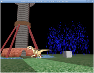
In the simplest case, you just create TCastleWindow instance
which gives you a ready-to-use scene manager inside
the TCastleWindow.SceneManager property.
Example code below uses scene manager to trivially make a full 3D model viewer. This correctly handles collisions, renders in an optimal manner (frustum culling etc.), handles animations and interactive behavior and generally takes care of everything.
var
  Window: TCastleWindow;
  Scene: TCastleScene;
begin
  Scene := TCastleScene.Create(Application
    { Owner that will free the Scene });
  Scene.Load('models/boxes.x3dv');
  Scene.Spatial := [ssRendering, ssDynamicCollisions];
  Scene.ProcessEvents := true;

  Window := TCastleWindow.Create(Application);
  Window.SceneManager.Items.Add(Scene);
  Window.SceneManager.MainScene := Scene;

  Window.OpenAndRun;
end.
The source code of this program is in
examples/3d_rendering_processing/view_3d_model_basic.lpr in engine sources.
You can compile it and see that it actually works.
There's also more extensive demo of scene manager in the
examples/3d_rendering_processing/scene_manager_demos.lpr,
and demo of other engine stuff in
examples/3d_rendering_processing/view_3d_model_advanced.lpr.
This looks nice and relatively straightforward, right? You create
3D object (Scene), and a window to display the 3D world
(Window). It's obvious how to add a second 3D object:
just create Scene2, and add it to
Window.SceneManager.Items.
The Lazarus component equivalent to TCastleWindow
is called TCastleControl. It works the same, but you
can drop it on a Lazarus form.
A 3D object is anything descending from a base class
T3D. All 3D objects in our engine are
derived from the T3D class.
The most important non-abstract 3D objects are TCastleScene
(3D model, possibly interactive VRML / X3D) and
TCastlePrecalculatedAnimation (non-interactive animation).
There are also some helper 3D objects
(T3DList - list of other 3D objects,
and T3DTranslated - translated other 3D object).
And the real beauty is that you
can easily derive your own T3D descendants,
just override a couple methods and you get 3D objects that can be visible,
can collide etc. in 3D world.
Any T3D descendant may be added to the scene manager
Items.
In every 3D program you have an instance of scene manager
(TCastleSceneManager class,
or your customized descendant of it),
and you add your 3D objects to the scene manager.
Scene manager keeps the whole knowledge about your 3D world,
as a tree of T3D objects.
Scene manager should also be present on the Controls
list of the window, to receive all the necessary events from your window,
and pass them to all interested 3D objects.
If you use TCastleWindow, suggested in the example above,
then scene manager is already created and added to the Controls
list for you. Scene manager also connects your camera,
and defines your viewport where 3D world is rendered through this camera.
For more advanced uses, you may use
TCastleCustomWindow, which doesn't create scene manager
automatically for you. Instead, you have to create and manage scene manager
instance yourself. You create yourself an instance of TCastleSceneManager
(or any descendant of this class), and you add it to
TCastleCustomWindow.Controls.
This is slightly more complex, but also allows more flexibility:
You can implement and use your own descendant of
TCastleSceneManager, overriding some methods, and thus making some special rendering tricks.Sometimes, you don't want your scene manager to be present on controls all the time. For example, if you create new scene manager for every level of your game, you probably want to manually remove/add chosen scene manager instance from/to
TCastleCustomWindow.Controls.
Example using this approach:
var
  Window: TCastleWindowCustom;
  SceneManager: TCastleSceneManager;
  Scene: TCastleScene;
begin
  Scene := TCastleScene.Create(Application
    { Owner that will free the Scene });
  Scene.Load('my_scene.x3d');
  Scene.Spatial := [ssRendering, ssDynamicCollisions];
  Scene.ProcessEvents := true;

  SceneManager := TCastleSceneManager.Create(Application);
  SceneManager.Items.Add(Scene);
  SceneManager.MainScene := Scene;

  Window := TCastleWindowCustom.Create(Application);
  Window.Controls.Add(SceneManager);
  Window.InitAndRun;
end.
This still looks relatively straightforward, right? You create
3D object (Scene), you create 3D world
(SceneManager), and a window to display the 3D world
(Window).
The Lazarus component equivalent to TCastleWindowCustom
is called TCastleControlCustom.
A related topic is the 2D controls management. This is quite similar to the scene manager approach, except that now it's for 2D and some details are different.
Everything that has to receive window events must derive from
TUIControl class. For example TCastleOnScreenMenu,
and TCastleButton are all descendants of
TUIControl. Even the TCastleSceneManager
is TUIControl descendant, since
scene manager by default acts as a viewport (2D rectangle)
through which you can see your 3D world.
To actually use the TUIControl,
you add it to the window's Controls list.
If you use Lazarus component, then you're interested
in TCastleControlCustom.Controls
list. If you use our own window library, you're interested in
the TCastleWindowCustom.Controls.
Once control is added to the controls list, it will automatically
receive all interesting events from our window.
A viewport is just a 2D rectangular control that provides a view
of 3D world.
As said previously, scene manager by default acts as a viewport.
But you can also have additional, custom viewports, offering simultaneous
different views of the same 3D world. This is done by the
TCastleViewport class.
You can have many viewports on the 2D window to observe your 3D world from various cameras. You can make e.g. split-screen games (each view displays different player), 3D modeling programs (where you usually like to see the scene from various angles at once), or just show a view from some special world place (like a security camera).
Your viewports may be placed in any way you like on the screen, they can even be overlapping (one viewport partially obscures another). Each viewport has it's own dimensions, own camera, but they can share the same 3D world (the same scene manager). Each viewport has also it's own rendering methods, so you can derive e.g. a specialized viewport that always shows wireframe view of the 3D world.
The scene manager itself also acts as a viewport,
if DefaultViewport is true. This is comfortable
for simple programs where one viewport is enough.
When DefaultViewport is false,
scene manager is merely a container for your 3D world,
referenced by custom viewports (TCastleViewport classes).
See the example in engine sources
examples/3d_rendering_processing/multiple_viewports.lpr
for demo of using custom viewports.
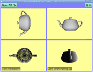
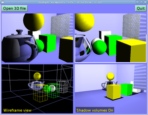
Table of Contents
This and the following chapters will describe how our VRML engine works. We will describe used data structures and algorithms. Together this should give you a good idea of what our engine is capable of, where are it's strengths and weaknesses, and how it's all achieved.
In this document we should not go
into details about some ObjectPascal-specific language constructs
or solutions — this would be too low-level stuff, uninteresting
from a general point of view. If you're an ObjectPascal programmer
and you want to actually use my engine then you may find it helpful
to study
source code (especially example programs in examples
subdirectories) and
units reference while reading this document.
If you only want to read this document, everything that you need
is some basic idea about object-oriented programming.
The base class of our engine is the TVRMLNode
class, not surprisingly representing a VRML node. This is an abstract
class, for all specific VRML node types we have some descendant
of TVRMLNode defined. Naming convention for non-abstract
node classes is like TNodeCoordinate class for VRML
Coordinate node type.
Every VRML node has it's fields available in it's
Fields property. You can also access
individual fields by properties named like FdXxx,
for example FdPoint is a property of
TNodeCoordinate class that represents
point field of Coordinate node.
VRML 1.0 children nodes are accessed by Children
and ChildrenCount properties.
For VRML 2.0 this is not needed, since you access all children nodes
by accessing appropriate SFNode and MFNode
fields. A convenience properties named
SmartChildren and SmartChildrenCount
are defined: for “normal” VRML 2.0 grouping nodes
(this mostly means nodes with MFNode field named
children) the SmartChildrenXxx
properties operate on appropriate MFNode, for other
nodes they operate on VRML 1.0 ChildrenXxx properties.
Because of DEF / USE mechanism
each node may be a children (“children” both in the
VRML 1.0 and 2.0 senses) of more than one node. This means that
we cannot use some trivial destructing strategy. When we destruct
some node's instance, we cannot simply destruct all it's children,
because they are possibly used in other nodes. The simple solution
to this is to keep track in each node about it's parents.
Each node has properties ParentNodes
and ParentNodesCount that track information about
all the nodes that use it in VRML 1.0 style (i.e. on
TVRMLNode.Children list). And properties
ParentFields
and ParentFieldsCount that track information about
all the SFNode and MFNode
fields referencing this node. The children node is automatically destroyed
when it has no parents — which means that
both ParentNodesCount and
ParentFieldsCount are zero.
Effectively, we implemented reference-counting.
And as a bonus, ParentXxx properties are sometimes
helpful when we want to do some “bottom-to-top”
processing of VRML graph (although this should be generally avoided,
“top-to-bottom” processing is much more in the spirit
of the VRML graph).
Classes for VRML nodes specific to particular VRML version
get a suffix _1 or _2 representing
their intended VRML version. For example, we have
TNodeIndexedFaceSet_1 (for VRML 1.0) and
TNodeIndexedFaceSet_2 (for VRML 2.0) classes.
Such nodes always have their ForVRMLVersion method
overridden to indicate in what VRML version they are allowed to be used.
For example, when parser starts reading IndexedFaceSet
node, it creates either TNodeIndexedFaceSet_1 or
TNodeIndexedFaceSet_2, depending on VRML version
indicated in the file header line. Note that this separation between VRML versions
is done only when reading VRML nodes from file. When processing
VRML nodes graph by code you can freely mix VRML nodes from various
VRML versions and everything will work, including writing nodes
back to VRML file (although if you mix VRML versions too carelessly
you may get VRML file that can only be read back by my engine, and not
by other engines that may be limited to only VRML 1.0 or only VRML 2.0).
More on this later in Section 3.2, “The sum of VRML 1.0 and 2.0”.
The result of parsing any VRML file is always a single
TVRMLNode instance representing the root node of the given file.
If the file had more than one root node [7]
then our engine wraps them in an additional Group
node. More precisely, additional instance of TVRMLRootNode
is created. It descends
from TNodeGroup_2 (but is suitable for all VRML/X3D versions).
This way it can always be treated as 100% normal Group
nodes. At the same time, VRML writing code can take special precautions
to not record these “fake” group nodes back to VRML file.
Our engine handles both VRML 1.0 and VRML 2.0. As we have seen in Chapter 1, Overview of VRML, there are important differences between these VRML versions. The way how I decided to handle both VRML versions is the more difficult, but also more complete approach. Effectively, you have the sum of VRML 1.0 and 2.0 features available.
I decided to avoid trying to create some internal conversions from VRML 1.0 to VRML 2.0, or VRML 2.0 to 1.0, or to some newly invented internal format. I wanted to have a full, flexible, 100% conforming to VRML 1.0 and VRML 2.0 specifications engine. And the fact is that any conversion along the way will likely cause problems — ideologically speaking, that's because there is always something lost, or at least difficult to recover, when a complicated conversion is done.
Practically here are some reasons why a simple conversion between VRML 1.0 and VRML 2.0 is not possible, in any direction:
VRML 2.0 specification authors intentionally wanted to simplify some things that people (both VRML world authors and VRML browser implementors) thought were unnecessarily complicated in VRML 1.0. This causes problems for a potential converter from VRML 1.0 to 2.0, since it will have trouble to express some VRML 1.0 constructs. For example:
In VRML 1.0 you can specify multiple materials for a single geometry node. In VRML 2.0 each geometry node uses at most one material. So a potential converter from VRML 1.0 to 2.0 may need to split geometry nodes.
In VRML 1.0 you can accumulate texture transformations (
Texture2Transformnodes). In VRML 2.0 you can't (you can only place oneTextureTransformnode in theAppearance.textureTransformfield). So a potential converter must accumulate texture transformations on it's own. And this is not trivial in a general case, because you can't directly specify texture transformation matrix in VRML 2.0. Instead you have to express texture transformation in terms of one translation, one rotation and one scaling.In VRML 1.0 you can specify any 4x4 matrix transformation using
MatrixTransformationnode. This is not possible at all in VRML 2.0. In VRML 2.0 geometry transformation must be specified in terms of translations, rotations and scaling.In VRML 1.0 you can limit which geometry nodes are affected by
PointLightorSpotLightby placing light nodes at particular points in the node hierarchy. That's because in VRML 1.0 light nodes work just like other “state changing” nodes: they affect all subsequent nodes, until blocked by the end of theSeparatornode.In VRML 2.0 this doesn't work. You cannot control what parts of the scene are affected by light nodes by placing light nodes at some particular place in the node hierarchy. Instead, you have to use
radiusfield of light nodes. This means that some VRML 1.0 tricks are simply not possible.OrthographicCamerais not possible to express using VRML 2.0 standard nodes.
Summary: in certain cases translating VRML 1.0 to 2.0 can be very hard or even impossible. If we want to handle VRML 1.0 perfectly, we can't just write a converter from VRML 1.0 to 2.0 and then define every operation only in terms of VRML 2.0.
On the other hand, VRML 2.0 also includes various things not present in VRML 1.0. This includes many new nodes, that often cannot be expressed at all in VRML 1.0: all sensors, scripts, interpolators, special things like
CollisionandBillboard.Moreover, VRML 2.0 uses
SFNode(with possibleNULLvalue) andMFNode, and generally reduces the state that needs to be remembered when processing VRML graph. This means that many existing features have to be expressed differently.For example consider specifying normals for
IndexedFaceSet. In VRML 2.0 everything that decides about how generated normals are supplied are thenormalandnormalIndexfields of givenIndexedFaceSetnode. We take advantage of theSFNodefield type, and say that wholeNormalnode may be just placed withinnormalfield ofIndexedFaceSet. So we just keep whole knowledge insideIndexedFaceSetnode.On the other hand, in VRML 1.0 we have to use the value of last
NormalBindingnode. This says whether we should use the lastNormalnode, and how.Potential VRML 2.0 to 1.0 converter would have to make a lot of effort to “deconstruct” VRML 2.0 shape properties back to VRML 1.0 state nodes. This makes conversion difficult to revert (e.g. when we want to write VRML 2.0 content back to file).
That's why I decided to support in my engine the sum of all VRML features.
For example, VRML 1.0 nodes can have direct children nodes, so I support it
(by Children property of TVRMLNode).
VRML 2.0 nodes can have children nodes through SFNode
and MFNode fields, so I support it too.
I'm not trying hard to “combine”
these two ideas (direct children nodes and children inside
MFNode) into one
— I just implement and handle them both
[8].
In some cases this approach forces me to do more work. For example, for many routines that calculate bounding boxes of geometry nodes, I had to prepare three routines:
Common implementation, as a static procedure inside the
X3DNodesunit. This handles actual calculation and as parameters expects already calculated properties of given shape. As a simple example, when calculating bounding box of a cube, we expect to get three parameters describing cube's sizes in X, Y and Z dimension.VRML 1.0 implementation in VRML 1.0-specific node version that calls the common implementation, after preparing parameters for common implementation. As a simple example,
TNodeCube_1(VRML 1.0 cube) just uses it'sFdWidth,FdHeightandFdDepthas appropriate sizes.And VRML 2.0 implementation in VRML 2.0-specific node version, that also calls the common implementation after preparing it's parameters. As a simple example,
TNodeBox(VRML 2.0 cube) accesses three items of it'sFdSizefield to get the appropriate sizes.
In our simple example above we talked about a cube,
and the whole issue with calculating three size values differently
for VRML 1.0 and 2.0 was actually trivial.
But the point is that for some nodes,
like IndexedFaceSet, this is much harder.
For VRML authors this “sum” approach means that when reading VRML 1.0, many VRML 2.0 constructs (that not conflict with anything in VRML 1.0) are allowed, and the other way around too. That's why you can actually mix VRML 1.0 and 2.0 code in my engine.
Update in 2022: As VRML 1.0 format is now ancient and maintaining it has been some work, this "sum" feature has been a little "downgraded". It is still possible to use many VRML 2.0 / X3D nodes in VRML 1.0, but not the other way around. That is, you can no longer use VRML 1.0 nodes in files declared as VRML 2.0 / X3D.
This also means that you have many VRML 2.0 features available
in VRML 1.0. VRML 2.0 nodes like Background,
Fog and many others, that express features not available
at all in standard VRML 1.0, may be freely placed inside VRML 1.0 models
when using our engine.
Also including (using WWWInline or
Inline nodes) VRML 1.0 files within VRML 2.0
files (and the other way around) is possible. Each VRML file will
be parsed taking into account it's own header line, and then included
content is actually placed as a children node of including
WWWInline or Inline node.
So you get VRML graph hierarchy with nodes mixed from both VRML versions.
You can create a node using CreateParse
constructor to parse the node. Or you can initialize node
contents by parsing it using Parse method.
However, these both approaches require you to
first prepare appropriate TX3DLexer
instance and a list of read node names.
There are comfortable routines like ParseVRMLFile
that take care of this for you. They create appropriate lexer,
and may create also suitable TStream instance to read
given file content.
Some details about parsing:
Our VRML/X3D lexer is a unified lexer for both VRML 1.0, 2.0 and (classic) X3D. Most of the syntax is identical, minor differences can be handled correctly by a lexer because it always knows VRML/X3D header line of the given file. So it knows what syntax to expect.
VRML/X3D version of the original file is saved in
TVRMLRootNode.ForceVersion. This will be used later when saving. Parser always returnsTVRMLRootNodeinstance, this keeps some per-file settings like version and X3D profile, components and meta values.When saving, you can save any
TVRMLNodeinstance to file. If it is notTVRMLRootNode, or ifTVRMLRootNode.HasForceVersionis false, we simply assume it uses the latest X3D version.In engine versions <= 2.5.0 we experimented with auto-detecting the suitable VRML/X3D version for nodes inside, but this mechanism was dropped. It was complicated, and was failing anyway for complicated cases (nodes from mixed versions, things with routes, imports, exports etc.). If you want to save a specific VRML/X3D version, it's best to simply wrap it inside
TVRMLRootNodeand force desired version explicitly. Modern programs should target only X3D anyway, as VRML 1.0 is ancient, and VRML 2.0 is old too (from 1997).While parsing,
ForVRMLVersionmethod mentioned earlier may be used to decide which node classes to create based on VRML/X3D version indicated in the file's header line.To properly handle DEF / USE mechanism we keep a list of known node names while parsing. After a node with
DEFclause is parsed we add the node name and it's reference toNodeNameBindinglist that is passed through all parse routines. When aUSEclause is encountered, we just search this list for appropriate node name.Simple VRML rules of
DEF/USEbehavior make this approach correct. Remember that VRML name scope is not modeled after normal programming languages, where name scope of an identifier is usually limited to the structure (function, class, etc.) where this identifier is declared. In VRML, name scope always spans to the end of whole VRML file (or to the nextDEFoccurrence with the same name, that overrides previous name). Also, the name scope is always limited to the current file — for example, you cannot use names defined in other VRML files (that you included byInlinenodes, or that include you). (Prototypes and external prototypes in VRML 2.0 are designed to allow reusing VRML code between different VRML files.)The simple trick with adding our name to
NodeNameBindingafter the node is fully parsed prevents creating loops in our graph, in case supplied VRML file is invalid.
SaveToStream method of TVRMLNode
class allows you to save node contents (including children nodes) to any stream.
Just like for reading, there are also more comfortable routines for writing
called SaveToVRMLFile.
When writing we also keep track of all node names defined
to make use of DEF / USE mechanism. If we want to write a named node,
we first check NodeNameBinding list whether the same name
with the same node was already written to file. If yes, then we
can place a USE statement, otherwise we have
to actually write the node's contents and add given node to
NodeNameBinding list.
The advantages of above NodeNameBinding
approach is that it always works correctly.
Even for node graphs created by code
(as opposed to node graphs read earlier from VRML file).
If node graph was obtained by reading VRML file, then the
DEF / USE statements will be correctly written back to the file, so there will
not be any unnecessary size bloat. But note that in some cases
if you created your node graph by code then some node contents
may be output more than once in the file:
First of all, that's because we can use DEF / USE mechanism only for nodes that are named. For unnamed nodes, we will have to write them in expanded form every time. Even if they were nicely shared in node graph.
Second of all, VRML name scope is weak and if you use the same node name twice, then you may force our writing algorithm to write node in expanded form more than once (because you “overridden” node name between the first
DEFclause and the potential place for correspondingUSEclause).
So if you process VRML nodes graph by code and you want to maximize the chances that DEF / USE mechanism will be used while writing as much as it can, then you should always name your nodes, and name them uniquely.
It's not hard to design a general approach that will always
automatically make your names unique. VRML 97 annotated
specification suggests adding to the node name an _ (underscore)
character followed by some integer for this purpose. For example,
in our engine you can enumerate all nodes (use EnumerateNode
method), and for each node that is used more than once (you can
check it easily: such node will have ParentNodesCount + ParentFieldsCount > 1)
you can append '_' + PtrUInt(Pointer(Node)) to the
node name. The only problem with this approach (and the reason why
it's not done automatically) is that you will have to strip
these suffixes later, if you will read this file back
(assuming that you want to get the same node names).
This can be easily done (just remove everything following the last underscore
in the names of multiply instantiated nodes).
But then if you load the created VRML file into some other
VRML browser, you may see these internal suffixes anyway.
That's why my decision was that by default such behavior is not done.
So the generated VRML file will always have exactly the same node
names as you specified.
As was mentioned a couple of times earlier, we do everything to get the VRML scene graph in memory in exactly the same form as was recorded in VRML file, and when writing the resulting VRML file also directly corresponds (including DEF / USE mechanism and node names) to VRML graph in memory.
Actually, there are two exceptions:
Inlinenodes load their referenced content as their childrenWhen reading VRML file with multiple root nodes, we wrap them in additional
Groupnode
... but we work around these two exceptions when writing VRML files. This means that reading the scene graph from file and then writing it back produces the file with the exact same VRML content. But whitespaces (including comments) are removed, when writing we reformat everything to look nice. So you can simply read and then write back VRML file to get a simple VRML pretty-printer.
This feature was mentioned a couple of times before.
In code, you can simply instantiate any nodes you want, you can
add them as a children of other nodes, you can set their
fields as you like, and so on. Also several methods for
enumerating and searching the nodes graph are provided
(like EnumerateNodes and FindNode).
See units
reference for details.
I made a decent converter from 3DS, Wavefront OBJ and other file formats to X3D this way. Once I was able to read these files, it was trivial to construct according VRML/X3D graphs for them. You can then save constructed VRML/X3D graph to a file (so user can actually use this converter) and you can further process and render them just like any other VRML nodes graph (so my engine seamlessly handles 3DS and Wavefront files too, even though it's almost solely oriented on VRML).
This also allows authors to include 3DS, Wavefront OBJ
and other files inside VRML/X3D files by Inline nodes,
making it possible to create scenes in mixed 3D formats.
Traversing VRML graph means visiting
all active VRML graph nodes in a depth-first search order.
By “active” nodes we mean that only the visible
(or affecting the visible) parts of the graph are browsed —
for example, only one child of a Switch
and LOD nodes is visited.
You can traverse nodes using Traverse
or TraverseFromDefaultState methods.
For each visited node, a callback function will be called.
The most important feature of traversing is that whole VRML state that we talked about in Section 1.5, “VRML 1.0 state” is collected along the way. For each visited node traverse callback gets all the information about accumulated transformation, active light nodes and (meaningful only for VRML 1.0 nodes) currently bound property nodes (material, texture etc.).
An important descendant of TVRMLNode is
the TVRMLGeometryNode class. This is an abstract
class. All visible VRML nodes (in VRML 1.0 and 2.0) are descendants of this class.
TVRMLGeometryNode class defines a couple of
important methods,
overridden in each descendant. All of these methods take
a State parameter that describes
VRML state at given point of the graph
(this is typically obtained by a traverse callback),
since we need this to have full knowledge about node's geometry.
LocalBoundingBox and
BoundingBox methods calculate axis-aligned
bounding box of given node.
Axis-aligned bounding box is one of the
simplest bounding volume types. It's a cuboid with axes aligned
to base coordinate system X, Y and Z axes. It can be easily
expressed as a pair of 3D points. In our engine we require
that the points' coordinates are correctly ordered, i.e.
X position of the first point must always be less or equal than
the X position of the second point, and analogously for Y and Z
values. We also have the special value for designating empty
bounding box. And while we're talking about empty bounding boxes,
remember to not confuse empty box with a box with zero
volume: a box with zero volume still has some position.
For example, a PointSet VRML node with only
one point has a non-empty bounding box with a zero volume.
A PointSet without any points has empty
bounding box.
I chose axis-aligned bounding boxes just because they are very simple to calculate and operate on. They have some disadvantages — as with all bounding volumes, there is some compromise between how accurately they describe bounding volumes and how comfortable it is to operate on them. But in practice they just work fast and are enough accurate.
LocalBoundingBox method returns a bounding
box of given object without transforming it (i.e. assuming that
State contains an identity transformation).
BoundingBox method
takes current transformation into account. Each descendant
has to override at least one of these methods.
If you override only LocalBoundingBox then
BoundingBox will be calculated by transforming
LocalBoundingBox (which can give poor bounding
volume, much larger than necessary).
If you override only BoundingBox then
LocalBoundingBox will be calculated by
calling BoundingBox with transformation matrix
set to identity matrix (this can make LocalBoundingBox
implementation much slower than a potential special
LocalBoundingBox implementation that knows that
there is no transformation, so no matrix multiplications have to be done).
VerticesCount and
TrianglesCount calculate triangles
and vertices count of given geometry.
LocalTriangulate and
Triangulate methods are available in the TShape
class. They calculate all the triangles of given geometry.
Use TShape.GeometryArrays if you want the full
information about every shape (including indexes, colors,
and all the other information required for efficient rendering).
If you want to control how detailed the triangulation should be:
Programmers can use
DefaultTriangulationSlices,DefaultTriangulationStacksandDefaultTriangulationDivisionsglobal variables.VRML / X3D authors can use the Geometry3D component - extensions: custom triangulation fields in node to control this.
Finally, my programs view3dscene and rayhunter allow you to control this by command-line options
--detail-quadric-slices <integer>
--detail-quadric-stacks <integer>
--detail-rect-divisions <integer>
This is a string property that specifies base URL of each node.
Actually, for now our engine doesn't support downloading data using
any network protocol,
so this is always treated just like an absolute path
on local file-system. It is always set to the directory of VRML file from which given
node was read. It's used by nodes that reference any external file,
like Inline or ImageTexture.
Thanks to this field, all such nodes can always resolve their
url fields with respect to the directory of their
file.
For example, assume that inside some directory you have a main VRML file
main.wrl and two subdirectories: textures
and inline. Inside textures you
have a file my_texture.png and inside
inline you have VRML file
textured_box.wrl. Finally, let's say that
you want to include textured box in main.wrl file,
so you write
Inline { url "inline/textured_box.wrl" }
Now inside textured_box.wrl you should reference
the texture like
ImageTexture { url "../textures/texture.png" }
and everything will work when you open main.wrl VRML file.
Moreover, textured_box.wrl is able to “stand
on it's own” too, which means that you can open only
textured_box.wrl and texture will still be properly
read.
This is similar to xml:base
attribute in XML, that was needed to make including XML files by XInclude
and referencing external files from various elements (like DocBook's
imagedata) to cooperate seamlessly.
At the end it's worth noting that you're not limited to the
nodes defined by VRML specifications and implemented in X3DNodes
unit. You can freely define your own TVRMLNode descendants.
All it takes to make them visible is to register them in
NodesManager object. For example, call
NodesManager.RegisterNodeClasses([TNodeMy]);
from your unit's initialization section. You may also want to add
it to the AllowedChildrenNodes list.
This way you can define specific VRML nodes for a specific
programs, without the need to modify anything within the base units.
I used this technique in the
malfunction game to define special-purpose VRML nodes like
MalfunctionLevelInfo and
MalfunctionNotMovingEnemy.
If you want to operate on the VRML graph, for
some purposes it's enough to load your scene to a
TVRMLNode instance.
This way you know the root node of the scene. Each node points
(within it's Children property and SFNode
and MFNode fields) to it's children nodes,
so if you know the root node of the scene, you know the whole
scene. TVRMLNode class gives you
many methods to operate on the nodes graph, and sometimes this is all you need.
However, some operations cannot be implemented in
TVRMLNode class. The basic reason is that the node
doesn't “know” the state of VRML graph where it
is used. Node's state is affected by other nodes that may be it's
parents or siblings. Moreover, a node may be used many times in the
same scene (by DEF / USE mechanism),
so it may occur many times in a scene with different states.
That's why many TVRMLNode methods
(like Triangulate and BoundingBox
methods described in Section 3.7, “Geometry nodes features”) require
a parameter State: they are not able to figure it
out automatically.
These are the reasons why an additional class, called
TCastleSceneCore, was created. It is essentially
just a wrapper around a VRML root node (kept inside it's
RootNode property) adding a lot of useful
and comfortable methods to operate and investigate the scene as a whole.
First, let's introduce a building block for our scene class:
a shape. Instance of TShape
class. Shape is basically two pieces of information: a geometry node
(TVRMLGeometryNode) and it's state
(TX3DGraphTraverseState).
For VRML >= 2.0, this usually corresponds to
a single instance of actual VRML Shape node,
that's the reason for it's name.
Shape contains absolutely all the information needed to render and generally deal with this piece of VRML graph. It's completely independent from other shapes.
For VRML 2.0, some shape features were
already available. That's because of smart definitions of
children fields of grouping nodes, as explained earlier in
Section 1.5.1, “Why VRML 2.0 is better”: we don't
need so much state information in VRML 2.0 and we can pick
children of grouping nodes in any order. Still, our shape provides
the more complete solution: it includes also accumulated transformation matrix and
“global” properties (fog and active lights).
This is the main property of TCastleSceneCore.
The idea is simple: to overcome
the problems with VRML state, we can just use Traverse
method from the root node (see Section 3.6, “Traversing VRML graph”)
and store every geometry node (descendant of TVRMLGeometryNode,
see Section 3.7, “Geometry nodes features”) along with it's state.
As a result we get a simple list of shapes.
This list is, to some extent, an alternative “flattened”
representation of the VRML graph.
Actually, we can't really have a completely flat list of shapes.
Instead, we create
a simple, usually quite flat tree of shapes, in TCastleSceneCore.Shapes.
Reason: some things, like Switch node, require some
processing each time we want to browse the tree (this way, we keep track
of shapes in inactive Switch children, which allows
us very fast switching of Switch.whichChoice,
that is: replacing/adding/removing large parts of VRML graph).
So we take VRML nodes graph, and transform it into another graph (shapes tree)... But the resulting tree is really much simpler, it's just as simple representation of VRML visible things as you can get.
This way we solve various problems mentioned in Section 1.5, “VRML 1.0 state”: we get full accumulated VRML state readily available for each shape. Also, given a tree of shapes, we can pick our shapes in any order, and we can pick any of them. This is crucial for various OpenGL rendering features and optimizations.
Additional advantage of looking at our shapes tree
is that resources completely not used (for example Texture2
node not used by any node in VRML 1.0) are not present there.
They don't occur in a state of any shape.
So unused textures will not be even loaded from their files.
Finally, remember that in Section 1.5, “VRML 1.0 state”
we mentioned a practical problem of simple VRML 1.0 implementation
in OpenGL: OpenGL stack sizes are limited. Our scene solves this,
because there is no unlimited push/pop hierarchy anymore.
Features of nodes like VRML 1.0 Separator
and TransformSeparator are already handled
at this stage. And they are handled without using any OpenGL stacks,
since this unit can't even depend on OpenGL. Features of VRML 2.0
Transform nodes that apply transformation
to all it's children are already handled here too.
TCastleSceneCore is responsible for implementing
most of the events mechanism of VRML / X3D.
Just set ProcessEvents
property to true.
Some underlying parts of events mechanism are in fact implemented
at the lower level, that is inside TVRMLNode class
and friends. For example, event routes are instantiated when reading VRML file
and they become attached to VRML graph. So passing events through routes
is already working at this point. Also, exposed events
are implemented directly inside TX3DField. So setting
an exposed field by eventIn causes appropriate behavior
(changing field's
value and generating proper eventOut).
However, without TCastleSceneCore.ProcessEvents,
all these routes and exposed events are useless, since nothing initially
“fires” the event. Routes and exposed events are mechanisms
to process events, but they cannot generate events “on their own”,
that is they generate events only when other events push them to it.
The way to make an “initial event” in VRML / X3D is to use
sensor nodes. Various sensor nodes
emit events at specified situations, for example
TimeSensorfires events continuously when time changes,KeySensorfires events when user presses a key within VRML browser,TouchSensorand others from “pointing device sensor component” in X3D fire events when user clicks / drags with mouse,ProximitySensorandTransformSensorfire events on collision (of viewer or normal objects within VRML world) with user-defined boxes in space, thus allowing collision detection to VRML authors.
By setting TCastleSceneCore.ProcessEvents to true
(and updating TCastleSceneCore.WorldTime,
TCastleSceneCore.KeyDown and others) you make sensors
work. Thus initial events are generated when appropriate, and
routes and exposed events take care of spreading them, changing VRML graph
as necessary.
Numerous other features are available in our scene class:
Methods to calculate bounding box, vertexes count and triangles count of the whole scene. They work simply by summing appropriate results of all shapes.
Methods to calculate triangles list (triangulate all shapes in the scene) and to build octrees for the scene. There are also comfortable properties to store the build octree associated with given scene — although our engine doesn't limit how you manage the constructed octrees, you can create as many octrees for given scene as you want and store them where you want.
More about octrees in Chapter 4, Octrees.
Methods to find
Viewpointor camera nodes, transform them, and calculate simple (position, direction, up) triple describing camera setting.Methods to find
Fognode and calculate it's transformation.
Some scene properties are quite time-consuming
to calculate. Calculating the tree of shapes
requires traversing whole scene graph. Calculating scene bounding
box is even more difficult, since for each shape we must calculate
it's bounding box
(in fact calculation of scene bounding box as implemented
simply uses the shapes tree). Obviously we cannot repeat
these calculations each time we need these values. So the results
are cached inside TCastleSceneCore instance.
Most of the properties are cached: shapes, bounding boxes, vertexes and triangles counts, fog properties. Even triangles' lists may be cached if you want.
Also various properties for single shapes are cached
inside TShape instance: bounding box,
bounding sphere and triangle and vertexes counts. After all,
some of these operations are quite time-consuming by themselves.
For example to calculate bounding box of IndexedFaceSet
we have to iterate over all it's coordinates.
Direct changes to actual VRML nodes are not
automatically detected. In other words cache is not automatically
cleared on changes. Instead you have to manually call
TCastleSceneCore.ChangedField
(or eventually TCastleSceneCore.ChangedAll)
after changing some parts of the scene. Scene analyzes how this change
affects the rendered scene, and invalidates as few as possible parts
of the cache.
For example changes to VRML 1.0 nodes like Texture2 or
Material will affect
only the shapes that have these nodes in their
state. So the whole shapes tree doesn't need to be
regenerated, also the information about other shapes
(like their bounding boxes) is still valid.
For simple scene changes, you can also use TX3DField.Send
methods. This will change the value of the field,
and automatically notify all interested scenes.
You can also just send events instead of directly modifying fields,
see the next section.
In Section 6.4, “VRML scene class for OpenGL” we will introduce the
TCastleScene class
that descends from TCastleSceneCore.
It adds various OpenGL methods and caches various OpenGL resources
related to rendering particular scene parts.
This means that our ChangedField method
will have even greater impact.
At the low level, passing events works by
TX3DEvent.Send method and
TX3DEvent.OnReceive callbacks.
Both input and output events can be send and received:
for input events, it's the outside world (routes, scripts)
that sends the event, and handling of the event is specific
to containing node. For output events, it's the other way around:
sending the event is specific to containing node, and the event
is received by connected routes.
When exposed fields are changed through events,
TCastleSceneCore takes care to automatically
internally call appropriate ChangedField methods.
This means that events mechanism automatically updates everything
as necessary, and you don't have to worry about it — the VRML
world inside TCastleSceneCore will just magically
change by itself, assuming TCastleSceneCore.ProcessEvents
is on. This also means that ChangedField methods
implement the “cherry-picking optimizations”
when VRML graph is changed: they know about what changed, and they
know how it affects the rest of the VRML graph, and so they decide
what needs to be recalculated. For example, when
Coordinate node changed through event,
we know that only geometry using this coordinate node has changed,
so only it's resources need to be recomputed.
There are a lot
of possibilities to optimize here by using knowledge about
what specific node does, what it possibly affects etc. VRML 2.0 things
are easier and probably more optimized in this regard
— reasons were given in
Section 1.5, “VRML 1.0 state”
and Section 1.5.1, “Why VRML 2.0 is better”.
So we have three methods of changing the field value. Do it directly, like
Field.Value := 666;
Scene.ChangedField(Field);
or do it by sending event, like
Field.EventIn.Send(666);
or use the simplest TX3DField.Send method,
that sends an event (or directly changes value, if events processing is turned off),
like
Field.Send(666);
This will trigger all event callbacks, so the field value will change,
and everyone interested will be notified about this: output event of exposed
field will be generated and sent along the routes,
and TCastleSceneCore will be notified about the change.
[7] Multiple root nodes are allowed in VRML 2.0 specification. Our engine also allows them for VRML 1.0 because it's an extension often expected by VRML 1.0 creators (humans and programs).
[8] SmartChildrenXxx properties
mentioned in the previous section somewhat combine
VRML 1.0 and 2.0 ideas of children nodes, but they are generally not used
except in some small pieces of code where they just make the code
shorter.
Table of Contents
Octree is a tree structure used to partition a 3D space. Each octree node has eight children (hence the name “octree”, oct + tree). Our engine uses octrees for a couple of tasks.
Generally speaking, octree is useful for various collision detection tasks:
First of all, for a “normal” collision detection needed in games. That is for checking collisions between the player and the world geometry. The player may be represented by a sphere, and when the player moves we check that:
The line segment between the current player position and the new player position does not collide with the world.
The sphere surrounding new player position does not collide with the world.
When we detect a collision, we can simply reject player move, or (much better) propose another, non-colliding new player position. This way the player can “slide” along the wall when he tries to move into it.
This is done within
MoveCollisionmethod of theTTriangleOctreeclass.Also, when gravity works, we want the player to preserve some preferred height above the ground. This allows the player to climb up and down the hills, stairs etc. It is often called terrain-following. This requires calculating current player height above the ground. By comparing this height with a preferred height we know whether the player position should fall down or raise up. This is done by checking for a collision between a ray (that starts at player's position and is directed down) with the world.
This is done by
HeightCollisionmethod ofTTriangleOctreeclass.For ray-tracer, this is the most important data structure. Ray-tracer checks collisions of rays with the world to calculate it's image. Also when calculating shadows we check for collision between light point (or a random point on light's surface, in case of surface lights) and the possibly shadowed geometry point.
This is done by
RayCollisionandSegmentCollisionmethods ofTTriangleOctreeclass.When player picks (for example by clicking with mouse) given point on the screen showing 3D scene, we want to know which object from our 3D scene (for example, which VRML node) he actually picked. So again we want to do collision detection between a ray (starting at player's position and with direction calculated from player's looking direction, screen dimensions and picked point coordinates on the screen) and the world.
Note that there are other methods to determine which object player picked. For example you could employ some OpenGL tricks: rendering in selection mode, or reading color buffer contents to get results of depth buffer tests. See The OpenGL Programming Guide - The Redbook for details. But once we have octree already implemented, it is usually easier and less cumbersome to use than these tricks.
When rendering using OpenGL, we don't want to pass to OpenGL objects that are known to be invisible to the player. For example, we know that objects outside of the camera frustum are invisible. In certain cases (when e.g. dense fog is used) we also know that objects further from player than certain distance are not visible.
This means that we want to check for collision between camera frustum and/or sphere with the world. This is done by
EnumerateCollidingOctreeItemsandSphereCollisionmethods.More information about how these algorithms are used will be given in Section 6.4, “VRML scene class for OpenGL”.
Octree is a tree where each internal (non-leaf) node has eight children.
Each node spans a particular space area, expressed
as an axis-aligned bounding box (available as Box
property of TOctreeNode).
Each node also has a chosen middle point inside this box (available
as MiddlePoint property of TOctreeNode
class). This point defines three planes parallel to the base
X, Y and Z planes and crossing this point.
Each child of given octree node represents one of the eight space parts
that are created by dividing parent space using these three planes.
Each child, in turn, may be either
Another internal node. So it has his own middle point and another eight children. His middle point must be within the space part that his parent node gave him.
Or a leaf, that simply contains actual items that you wanted to store in an octree. What is an “actual item” depends on with want items you want to calculate collisions using this octree.
In our engine we have two octree types:
TTriangleOctreethat keeps trianglesTShapeOctreethat keeps VRML shapes. Shape is a pair ofTVRMLGeometryNode(remember from Section 3.7, “Geometry nodes features” that these are the only VRML nodes that actually have some geometry visible) and it'sState(obtained from traversing VRML graph).
What happens when given item should be included in more than one children? That is, item is contained in space part of more than one children?
Simple solution is to put this item inside all children where it should be. This means that we could waste a lot of memory if given item should be present in many leaf nodes, but this problem can be somewhat cured by just keeping an array of octree items for the whole octree (like
TTriangleOctree.TrianglesorTShapeOctree.ShapesList) and keeping only indexes to this array in octree leafs (ItemsIndicesproperty ofTOctreeNode).Another possible solution is to keep such problematic item only in the list of items of internal node, instead of putting it inside children nodes. But each octree node has eight children, and given item can be contained for example only in two of eight children. In this case our collision checking routines would always have to consider this item, while in fact they should consider it only for a 2/8 part of the space.
That's why my engine doesn't use this approach. Note that some hybrid approach could be possible here, for example keep the item if it spans more than 4 children nodes and put it inside children otherwise. This idea remains to be implemented one day... For now our collision checking is fast enough for all purposes when it's needed in real-time games.
Example below shows an octree constructed by our engine. The sample scene contains two boxes and a sphere. On the screenshot yellow bounding boxes indicate every internal node and every non-empty leaf. Whole scene is contained within root node of the tree, so the largest yellow bounding box corresponds also to the bounding box of the scene. The “lonely” box (in the foreground) is placed within the two direct children on the root tree node. Left and right quarter on the image contain only empty children leaves of root node, so their bounding boxes are not shown. Finally, the interesting things happen in the quarter with a box and a sphere. Sphere has many triangles, so a detailed octree is constructed around it. Also the sphere caused a little more detailed octree around the near box.
#VRML V2.0 utf8

Viewpoint  {
  position -10.642 8.193 -5.614
  orientation -0.195 -0.921 -0.336 2.158
}

Transform {
  translation 4 0 1.25
  children Shape {
    appearance DEF ALit Appearance { material Material { } }
    geometry Sphere { }
  }
}

Transform {
  translation 4 0 4
  children Shape {
    appearance USE ALit
    geometry Box { }
  }
}

Transform {
  translation -4 0 -4
  children Shape {
    appearance USE ALit
    geometry Box { }
  }
}

You can view octree like this using view3dscene. Just turn on the menu option “View” -> “Show whole octree”. There are also menu commands to investigate octree nodes only at the particular depth.
Let's assume that you have some reference object (like a sphere or a ray or a line segment mentioned in the first section) that you want to check for collisions with all items contained in the octree. You start from the root node — all items, which means “all potential colliders”, are there. You check with which children of this node your object could possibly collide. Different object types will require various approaches here. In general, this comes down to checking for collision between children nodes' boxes and your reference object. For example:
For a sphere, you check which child node contains the sphere center. Then you check with which planes (of the three dividing planes of this node) the sphere collides. This determines all the children that the sphere can collide with.
Above approach is not as accurate as it could be — since it effectively checks the collision of the bounding box of the sphere with children boxes. To make it more accurate you can check whether the middle point of given node is within the sphere. But it's not certain whether this additional check will make your collision detection faster (because we will descend into less children nodes) or slower (because we spend time on the additional check). In practice, this depends on how large spheres you will check for collision — for small (small in comparison to the world) spheres, this additional check will seldom eliminate any child and probably will be worthless.
For a ray: determine child node where ray start is. Then check for collision between this ray and three base planes crossing node's middle point. This will let you determine into which children nodes the ray enters. Similar approach could be taken for the line segment.
For a frustum: first note that our engine stores frustum as a 6 plane equations.
The basic approach here is to employ the method of checking for collision between a plane and a box. To determine collision of a box with a plane you can check 8 box corners on which side of the plane they are (simply by checking expression similar to the plane equation, Ax + Bx + Cz + D >= 0). If all points are on the same side of the plane (and no point lies precisely on the plane) then there is no collision. This also tells your on which size of the plane the box is located, in case there is no collision.
In our engine, frustum planes are correctly oriented, so the answer to the question “on which size of the plane” a box is located is meaningful to us. To check for collision of frustum with a node, we check 6 frustum planes for collision with this node's box. If box is on the inside side of every plane, this means that the box is completely inside the frustum. Otherwise, if the box is on the outside side of at least one plane, then the box is completely outside of the frustum. Otherwise (which means that box collides with at least one plane, and it's not outside any plane) we don't really know.
In the last case, we're pretty certain that the box collides somehow with the frustum, so we assume this. In case of error, nothing terrible will happen: our collision checking routine using octree will just work a little slower than possible, but it will still be 100% correct. In practice, in almost all cases our assumption will be true, although some nasty cases are indeed possible. You can see an example of such case below. This is a side view showing a frustum and a box. You can see that the box collides with 3 planes and is considered to be on the inside of the 4th plane (the one at the bottom). You can easily extend this image to 3D and imagine the remaining 2 frustum planes in such way that they will intersect the box.
Figure 4.2. A nasty case when a box is considered to be colliding with a frustum, but in fact it's outside of the frustum
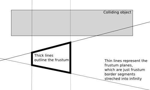
Once you can check with which octree node's children your object collides, you just apply this process recursively. That is, for each internal node you determine which of it's children may collide with your reference object, and recursively check for collisions inside these children. For each leaf node, you just sequentially check all it's items for collision. For example, in case of a triangle octree, in the leafs you will check for collision between triangles and your reference object.
What's the time of this collision checking algorithm? Like with all tree structures, the idea is that the time should be logarithmic. But actually we don't use any advanced techniques that could ensure that our octree is really balanced. And the fact that items that are put inside more than one children are effectively multiplied in the octree doesn't help either. However octrees of real-world models are enough balanced (and multiplication is small enough) to make collision checking using octrees “logarithmic (i.e. fast) in practice”.
Some more notes about collision checking using an octree:
Sometimes all you need is the information that “some collision occurred” (for example that's enough for shadow detection). Sometimes you want to get the closest collision point (for example, closest to the ray start, for ray-tracing). The first case can obviously be optimized to finish whole algorithm as soon as any collision is found. In the second case you must always check all items when you process a leaf node (because the items in leaf nodes are not ordered in any way). But when processing internal nodes it can still be optimized to not enter some children nodes if collision in earlier child node was found (in cases when we know that every possible collision in one child node must be closer to ray start than every possible collision in other node).
As was mentioned earlier, if an octree item fits into more than one child of given node, we put it inside every matching children node, thus duplicating information about this item in many leafs. But this means that we can lose some speed. We can be fooled into checking more than once for collision between our reference object (like a ray) with the same item, but placed within a different leaf.
This is not so terribly bad, since we are talking here about tests like checking for collision between a single ray and a single triangle. So this test is anyway quite fast operation, in constant time. But still it requires a couple of floating point operations, and it's called very often by our algorithm, so we want to optimize it.
The solution is called the mailboxes. Each octree item gets a mailbox. Each reference object (like a ray) gets a unique tag. Before we check for collision between our reference object and an octree item, we check whether the mailbox has the information about the collision test result for this object tag. If yes, then we obtain the collision test result from the mailbox. Otherwise, we perform normal (more time-consuming) test and we store the test result along with the object tag within the mailbox. This way each item will be tested for collision with reference object only once. Next time we will just use the mailbox.
This is possible to implement thanks to the fact that we keep indexes to items in octree nodes, and the actual items are kept in an array for a whole octree. So we can naturally place our mailboxes in this array.
A simple algorithm starts
with an empty tree, containing one leaf node with no items.
Then we add our items (triangles, VRML shapes etc.) to the octree
keeping an assertion that no leaf can have more than
some specified number of items (LeafCapacity
property of TOctree class).
When we see that adding another item to some leaf would break
this assertion, we convert the leaf to an internal node
with eight children, and we add items (previous leaf items
and the new item that we're trying to add) to newly created children.
Of course, each children gets only the items that are within its
space part.
Note that this algorithm doesn't guarantee in any way that
a tree is balanced. And we want the tree to be balanced,
otherwise checking for collisions using this tree will be as slow
(or even slower) than just sequentially checking collision with all items.
However, for most real-world models, the items are spread more-or-less
evenly across the scene, so in practice our tree is more-or-less balanced.
To prevent the pathological cases that could result in extremely deep octrees
we can add a simple limit on the allowed depth of the tree
(MaxDepth property of TOctree class).
When a leaf reaches MaxDepth, we will not split it
to an internal node anymore, no matter how many items does it contain.
So the assertion becomes “leafs on depth < MaxDepth
must have at most LeafCapacity items”.
This way the nasty cases are somewhat bounded —
our collision checking using tree cannot be much
slower than just sequentially checking for collision with all contained items.
There is a question how to calculate middle point of each node. The simple and most common approach is just to calculate it as an actual middle point of the node's box. Root tree node gets a box equal to the bounding box of our scene. But you could plug here other techniques. The basic idea is that the tree should be balanced, so ideally the middle point should divide the node's box into eight parts with equal number of triangles inside.
For some purposes it's helpful to keep in each internal node
a list of all items contained within it's children.
This eats more memory, but may allow in some
cases to terminate the collision checking operation faster.
For example, when we want to check which octree items are inside
a camera frustum, we often find ourselves in a situation when
we know that some octree node is completely contained within
the frustum. If we have all the items' indexes
easily accessible within this internal node, we can avoid
having to traverse all children nodes under this node.
This is used by TShapeOctree
in our engine.
In version 1.6.0 of the engine, the octree structures were much improved to make them suitable for dynamic scenes. The crucial idea is to use a 2-level hierarchy of octrees (instead of a single octree).
Each shape has it's own triangle octree, build and stored in local shape coordinates (
TShape.OctreeTriangles). Since everything inside this octree is stored in local coordinates, nothing has to be updated when merely the transformation of this shape changes (it's moved, rotated and such). When the local geometry changes, the octree still has to be rebuild — but now it's only the octree for this particular shape, octrees of other shapes don't change.There's also a single octree of all scene shapes. Shapes are stored there in world coordinates. Each change of geometry causes the rebuild of this octree, but this is a small octree, so rebuilding it is usually very fast.
When making a collision query, for example when testing whether a ray (given in world coordinates) intersects the scene, we start with a normal collision in the shape octree. At the leaves, we have a list of shapes potentially intersecting this ray. To test ray with each shape, we transform the ray into shape's local coordinates (this means we need to keep an inverted matrix of shape transformation, to convert from world space into local space). Then the ray in local coordinates is checked for collisions with triangle octree inside the shape. After the testing, we need to transform the returned intersection (if found) back into world coordinates.
I dare to say that this works pretty excellent. Traversing the shape
octree must be done efficiently, just like traversing triangles octree
— in fact, we simply have TBaseTrianglesOctree
class that implements the non-leaf traversing algorithms for both tree
kinds. Triangle/shape octrees only have to handle what happens in leaf
octree nodes. Both octrees use the mailbox
technique to avoid checking the same item more than
once during one collision query. For triangle octree mailboxes
save the number of direct triangle vs ray/segment tests.
For shape octree they save the number of shape vs ray/segment
tests (so we will have less queries to local shape octrees,
which is quite important saving, this makes query time more than 2 times
faster on some scenes).
As noted, we need to know the transformations and
inverted transformations of the shapes, to freely switch between world
and local coordinate space. For normal transformations (Transform
node in VRML >= 2.0) we simply calculate the inverted matrix along
with the normal matrix when traversing VRML/X3D graph, so when doing collision
query we have both matrices ready to use. For arbitrary 4x4 matrix
transformations (MatrixTransform node, standard in VRML 1.0,
and added as an extension to VRML >= 2.0) we have to actually calculate
matrix inversion. Careful reader will spot here potential problems:
What if the matrix is not reversible? What if there's a scale with zero factor, for example a scale
(1, 1, 0)that projects shape onto Z=0 plane?Well, then we'll have a problem... this is simply not solved now, and as far as I know it would just require special treatment (which is quite difficult, since there may be many such difficult transforms along the traversing way).
A minor problem is with arbitrary matrices, as they may change a point into a direction or the other way around (as we work with homogeneous coordinates, each 3D point is actually a 4D vector with non-zero 4th component; each 3D direction is a 4D vector with 4th component zero). This is simply detected and no collision assumed — we can't do anything more sensible for these cases actually. That's why I really like the fact that VRML >= 2.0 removed
MatrixTransformfrom the standard — forcing authors to express transformations in terms of onlyTransformnode is a Good Idea.Another problem is when we check for collisions with axis-aligned box or sphere. How to transform an axis-aligned box or sphere by a matrix?
An axis-aligned box should turn into an oriented box by a mere rotation. If we also take into account scaling along the arbitrary axis, you get something that doesn't even have to be a box. It's a 6-DOP, that is a set of 3 pairs of parallel planes. There are known routines to detect collisions with such thing, but admittedly they are a little more involved and, what's more important, much slower than routines dealing with simple axis-aligned box.
A sphere under an arbitrary transformation will turn into an ellipsoid. Ellipsoid is a sphere with (possibly) non-uniform scale along an arbitrary 3D axis. To make collisions with it you usually just un-rotate and un-scale the other object (like triangle) and then make normal intersection with a sphere. Again, this is doable, but is also slower (than normal, untransformed, sphere routines).
So what's our solution? Just ignore the whole issue. Transform axis-aligned box into another axis-aligned box, possibly enlarging it by the way. Convert sphere into axis-aligned box, and then transform this into possibly even larger axis-aligned box. This way we input an axis-aligned box into local sphere's octree. While this looks like a lame solution, it's also simple and fast. Practice shows that it's “lameness” is totally not noticeable on real 3D scenes. That's because boxes and spheres are used mainly as bounding volumes for player and creatures. So the fact that they grow slightly larger during collision detection is not noticeable in practice.
Still, implementing it better, at least using ellipsoids is of course planned some day. It just doesn't seem desperately needed now.
The goal is to implement one day a really dynamic octree, to avoid rebuilding the shape octree at all. For details, see the paper Dynamic Irregular Octrees (from the page http://www.cs.nmsu.edu/CSWS/php/techReports.php?rpt_year=2003) by Joshua Shagam and Joseph J. Pfeiffer. A short summary of the idea:
First of all, updating the octree can be done simply by deleting and re-inserting the octree item.
During delete and insertion you should try to keep the octree balanced, so leafs may be split or merged to keep octree limits (
maxDepth,leafCapacityin our implementation) satisfied. Inserting is of course already implemented (that's how we construct the octree), the delete operation must be done.To make the deletion possible in a reasonable time, you have to keep each item only once in the octree. This means that some items will not be placed at octree leaves, instead they will be “stuck” at the lowest possible internal node.
Note that this will also make the “mailbox” idea useless, as the only function of “mailbox” is to save the computation when items are duplicated many times in the octree.
The fact that some items get “stuck” at internal nodes is generally a bad thing. We want to move items as deep as possible, to gain from octree traversing. Otherwise the whole idea of octree becomes useless.
To counter this, we make the octree node planes optional. Since a plane may be “deactivated”, some items may be allowed to go deeper into the octree.
There are other tree structures similar to the octree. Generally, octree is the easiest one to construct. Other tree structures give greater flexibility how the space is partitioned on each level, but to actually get the significant speed benefit, these trees must be also constructed in much smarter way.
kd-tree partitions space at each node by a plane parallel to one of the base planes. In other words, it uses one plane where octree uses three planes. This allows greater flexibility, for example it may be more optimal to divide the space more often by a X = const plane than Y = const. Octree is forced to divide space by all three planes at each node.
If you will use the simple “rotational” strategy (X, Y, Z, then again X, Y, Z and so on) to choose partitioning axes at each depth, then the kd-tree becomes similar to an octree.
The name kd-tree comes from “k-dimensional tree” term, since kd-tree may be used for any number of dimensions, not necessarily 3D.
BSP (Binary Space Partitioning) tree partitions space in each node by a plane. Any plane, not necessarily parallel to one of the base X, Y, Z planes.
This gives even more flexibility than kd-tree, but it makes constructing optimal BSP trees much harder (assuming that you want to actually produce a better tree than what can be achieved with kd-tree). It also means that at each node you have to check for collision between your reference object and an arbitrary plane (instead of a plane parallel to one of the base coordinate system planes), so computations get a little slower than for kd-tree.
Note that BSP tree is suitable for any number of dimensions, just like kd-tree. You just use different equations to represent hyperplanes in other dimensions.
Finally, note that the only thing that ties octree to 3 dimensions is actually it's name. The same approach could be used for any number of dimensions. For N dimensions, each internal node will have 2N children. For example for 2 dimensions each node has 4 children, and such tree is called a quadtree.
Note that this approach is inadequate when we have a really large number of dimensions, because then 2N will be so large that “organizational” data of all tree nodes may eat a lot of memory. But it is not a problem if we stay within reasonable number of dimensions, like 2 or 3.
Table of Contents
This chapter describes our implementation of ray-tracer, along with some related topics.
We don't even try to explain here how ray-tracing algorithms work, as this is beyond the scope of this document. Moreover, the ray-tracer is not the most important part of our engine right now (OpenGL real-time rendering is). This means that while our ray-tracer has a couple of nice and unique features, admittedly it also lacks some common and important ray-tracer features, and it certainly doesn't even try to compete with many other professional open-source ray-tracing engines existing.
Many practical details related to using our ray-tracer are mentioned in rayhunter documentation. Many sample images generated by this ray-tracer are available in the rayhunter gallery.
The basic data structure for ray-tracing is an octree based on
triangles, that is TTriangleOctree instance.
If you want to ray-trace a scene, you have to first build
such octree and pass it to a procedure that
does actual ray-tracing. Note that the quality of the octree is critical
to the speed of the ray-tracer. Fast ray-tracer requires
much deeper octree, with less items in leafs (LeafCapacity
property) than what is usually sufficient for example
for collision detection in real-time game.
To calculate triangles for your octree you should use the
Triangulate method of VRML geometry nodes.
Triangles enumerated by this method should be inserted into the octree.
If you use TCastleSceneCore class to load
VRML models (described in Section 3.10, “VRML scene”)
you have a comfortable method CreateTriangleOctree
available that takes care of it all, returning the ready octree
for a whole scene.
The Triangulation method is also admittedly responsible
for some lacks in our ray-tracer. For example, ray-tracer doesn't handle
textures, because triangulation callback doesn't return texture coordinates.
Also normal vectors are not interpolated because triangulation callback
doesn't return normal vectors at the triangle corners.
This is all intended to be fixed one day, but for now ray-tracer is not
that important for our engine.
Classic Whitted-style deterministic ray-tracer is done
by TClassicRayTracer class in
RayTracer unit.
Point and directional lights are used, as defined by all normal
VRML light nodes. This means that only hard shadows are available.
Algorithm sends one primary ray for each image pixel.
Ray-tracing is recursive, where the ray arrives on some surface we check
rays to light sources and eventually we recursively check refracted ray
(when Material has
transparency > 0) and reflected ray
(when Material has mirror > 0).
The resulting pixel color is calculated according to VRML 97 lighting equations. This is probably the most important advantage of ray-tracer in our engine: ability to calculate images conforming precisely to the VRML 97 lighting specification. Actually, we modified these equations a little, but only because:
I have recursive ray-tracing while VRML 97 specifies only local light model, without a placeholder for reflected and refracted color.
VRML 1.0
SpotLightmust be calculated differently, since it uses thedropOffRatefield (a cosinus exponent) to specify spot highlight. While VRML 2.0 uses thebeamWidthfield (a constant spot intensity area and then a linear drop to the spot border). So for VRML 1.0 spot lights we use the equations analogous to the OpenGL lighting equations.The ambient factor is calculated taking into account that standard VRML 1.0 light nodes don't have the
ambientIntensityfield. Although, as an extension, our engine allows you to specifyambientIntensityto get VRML 2.0 behavior in VRML 1.0.
Done by TPathTracer class in
RayTracer unit.
Surface lights are used: every shape with non-zero
emissiveColor is considered a light emitter.
For each image pixel many random paths are checked and final pixel color
is the average color gathered from all paths.
Path length is determined by a given minimal path length and a Russian-roulette parameter. Every path will have at least the specified minimal length, and then Russian-roulette will be used to terminate the path. E.g. if you set minimal path length to 3 and Russian-roulette parameter to 0.5 then 1/2 of all paths will have length 3, 1/4 of all paths will have length 4, 1/8 of all paths will have length 5 etc.
Russian-roulette makes sure that the result is unbiased, i.e. the expected value is the correct result (the perfect beautiful realistic image). However, Russian-roulette introduces also a large variance, visible as a noise on the image. That's why forcing some minimal path length helps. Sensible values for minimal path length are around 1 or 2. Of course, the more the better, but it will also slow down the rendering. You can set minimal length to 0, then Russian-roulette will always be used to decide about path termination (expect a lot of noise on the image!).
Actually our path-tracer does something more than a normal
path-tracer should: for every pixel it checks
PrimarySamplesCount of primary rays,
and then each primary ray that hits something splits into
NonPrimarySamplesCount. So in total we check
PrimarySamplesCount *
NonPrimarySamplesCount paths.
This optimization comes from the fact that there is no need to take many
PrimarySamplesCount, because all primary rays hit
more-or-less the same thing, since they have very similar direction.
To get really nice results path-tracer requires a different
materials description. I added
a couple of additional fields to Material node
to describe physical material properties (for Phong's BRDF).
If these fields are not specified in Material node,
path-tracer tries to calculate them
from normal material properties, although this may result in a poor-looking
materials. There's also a program kambi_mgf2inv
available that let's you convert MGF files to VRML 1.0 generating correct
values for these additional Material fields.
Shadow cache is used, this makes path-tracer a little faster. Also you can generate the image pixels in more intelligent order than just line-by-line: you can use Hilbert or Peano space-filling curves. In combination with shadow cache this can make path-tracing faster (shadow cache should hit more often). Although in practice space-filling curves don't make any noticeable speed difference. Undoubtedly, there are many possibilities how to improve the speed of our path-tracer, and maybe one day space-filling curves will come to a real use.
Our ray-tracer can store images in the RGBE format.
RGBE stands for Red + Green + Blue + Exponent. It's an image format developed by Greg Ward, and used e.g. by Radiance. Colors in RGBE images are stored with a very good precision, while not wasting a lot of disk space. Good precision means that you may be able to expose in the image some details that were not initially visible for the human eye, e.g. by brightening some areas. Also color components are not clamped to [0; 1] range — each component can be any large number. This means that even if resulting image is too bright, and some areas look just like white stains, you can always correct the image by darkening it or applying gamma correction etc. This is especially important for images generated by path-tracer.
You can process RGBE images using various Radiance programs. You can also use RGBE images in all my programs, for example you can view them using glViewImage and you can use them as textures on VRML models.
This is a feature closely related to ray-tracer routines, although it doesn't actually involve any recursive ray-tracing. The idea comes from the realization that we already have a means to calculate light contribution on a given point in a scene, including checking what lights are blocked on this point. So we can use these methods to calculate lighting on some surface independent of the camera (player) position. All it takes is just to remove from lighting equations all components related to camera, which means just removing the specular component of lighting equation. We can do it even for any point on a scene (not necessarily a point that is actually part of any scene geometry), as long as we will provide material properties that should be assumed by calculation.
What do we get by this? We get the ability to generate textures that contain accumulated effect of all lights shining on given surface. This includes shadows. We can use such texture on a surface to get already precomputed lighting with shadows. Of course, the trick will only work as long as lights are static in the scene and it's not a problem to remove specular component for given surface. And remember to make the texture large enough — otherwise user will see that the shadows on the wall are pixelated and the whole nice effect will be gone.
I used this trick to generate ground texture for my toy lets_take_a_walk. Initially I had this model:
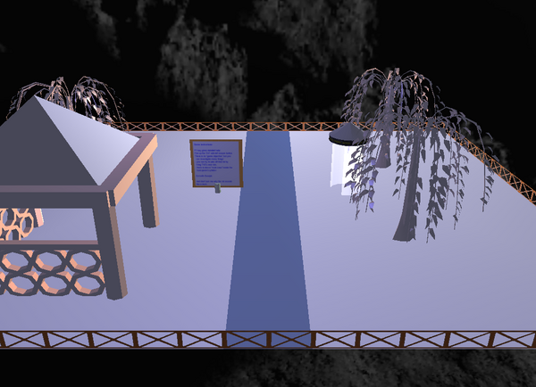
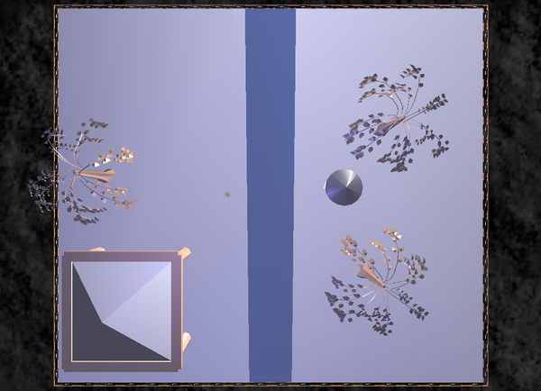
Using our trick I generated this texture for the ground. Note how the texture includes shadows of all scene objects. And note how the upper-right part of the texture has a nice brighter area. Our OpenGL rendering above didn't show this brighter place, because the ground geometry is poorly triangulated. So OpenGL rendering hit again the problems with Gouraud shading discussed in detail earlier in Section 3.7.2, “Triangulating”. It's a quite large texture (1024 x 1024 pixels), but any decent OpenGL implementation should be able to handle it without any problems. In case of problems, I would just split it to a couple of smaller pieces.

Finally, resulting model with a ground texture:
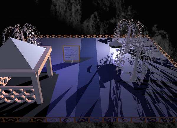
Such textures may be generated by the
gen_light_map program included in the
castle_game_engine/examples/vrml/tools/gen_light_map.lpr
file in our engine source code. The underlying unit responsible
for all actual work is called VRMLLightMap.
lets_take_a_walk source code is available too,
so you can see there an example how the gen_light_map
program may be called.
Table of Contents
When rendering using the OpenGL we try to get results as close as possible to the VRML 2.0 lighting equations and X3D lighting equations. We set OpenGL lights and materials properties to achieve the required look.
Note that there are bits when it is not possible to exactly match VRML 2.0 / X3D requirements with fixed-function rendering:
VRML 2.0 / X3D specify the spot light falloff by a
beamWidthfield. This cannot be precisely translated to a standard OpenGL spotlight exponent.Let α be the angle between the spot light's direction and the ray from spot light's position to the considered geometry point.
OpenGL spot light uses cosinus drop-off, which means that the light intensity within the spot
cutOffAngleis calculated as a Cos(α)spotExponent.VRML 2.0 / X3D have a
beamWidth. When α < beamWidth, the light intensity is constant (1.0). For larger angles, the intensity is linearly interpolated (down to 0.0) until angle reachescutOffAngle.
There is just no sensible translation from
beamWidthidea to OpenGLspotExponent.An exception is the case when beamWidth >= cutOffAngle. Then spot has constant intensity, which has be accurately expressed with GL_SPOT_EXPONENT = 0. Fortunately, this is the default situation for all spot lights.
We have considered an extension to define
SpotLight.dropOffRateas an extension for VRML >= 2.0 lights. With definition like “default value of dropOffRate = -1 means to try to approximate beamWidth, otherwise dropOffRate is used as an exponent”. But it didn't prove useful enough, especially since it would be our own extension.Looking at how other VRML/X3D implementations handle this:
Seems that most of them ignore the issue, leaving spot exponent always 0 and ignoring beamWidth entirely.
One implementation http://arteclab.artec.uni-bremen.de/courses/mixed-reality/material/ARToolkit/ARToolKit2.52vrml/lib/libvrml/libvrml97gl/src/vrml97gl/old_ViewerOpenGL.cpp checks beamWidth < cutOffAngle and sets spot_exponent to 0 or 1. This is what we were doing in engine versions <= 3.0.0.
Xj3D (see
src/java/org/web3d/vrml/renderer/ogl/nodes/lighting/OGLSpotLight.java) setsGL_SPOT_EXPONENTto 0.5 / beamWidth.It's not “more precise” in any way, the value 0.5 is just a "rule of thumb" as far as we know. But at least it allows to control exponent by
beamWidth. This is an important advantage, as you can at least change the drop off rate by changing the beamWidth. Even if beamWidth is not interpreted following the specification, at least it's interpreted somehow, and allows to achieve a range of different effects.FreeWRL (see http://search.cpan.org/src/LUKKA/FreeWRL-0.14/VRMLRend.pm,
freewrl-1.22.13/src/lib/scenegraph/Component_Lighting.cin later version) uses approach similar to Xj3D, settingGL_SPOT_EXPONENTto 0.5 / (beamWidth + 0.1).For example, this results in
beamWidth = 0 => GL_SPOT_EXPONENT = 5
beamWidth = Pi/4 => GL_SPOT_EXPONENT =~ 0.5 / 0.9 =~ 1/2
beamWidth = Pi/2 => GL_SPOT_EXPONENT =~ 0.5 / 1.67 =~ 1/3
It's similar to Xj3D, and the +0.1 seems to be just to prevent division by (something close to) zero in case beamWidth is very very small. Unfortunately, this addition also limits the possible values of
GL_SPOT_EXPONENT: it's at most 5 (0.5 / 0.1 = 5, as beamWidth must be > 0), and sometimes larger values would be useful.In our engine current version, we do it like this:
If beamWidth >= cutOffAngle, then GL_SPOT_EXPONENT is 0.
Otherwise we follow Xj3D version:
GL_SPOT_EXPONENTis 0.5 / max(beamWidth, epsilon)
If you want to convert VRML 1.0
dropOffRateto VRML 2.0 / X3DbeamWidthprecisely:If dropOffRate = 0, then leave beamWidth at default Pi/2. This makes beamWidth >= cutOffAngle (because cutOffAngle must be <= Pi/2 according to spec), which means no smooth falloff.
Otherwise beamWidth := 0.5 / (128 * dropOffRate) = 1 / (256 * dropOffRate).
The exponential fog of VRML 2.0 also uses different equations than OpenGL exponential fog and cannot be matched perfectly. See VRML and OpenGL specifications for details.
Fixed-function renderer uses Gouraud shading, with it's limitations.
Shader pipeline overcomes above problems. We program spot falloff
ourselves in GLSL, honoring beamWidth correctly.
We also do per-pixel lighting calculation (Phong shading).
See lighting.
You can also use classic ray-tracer of our engine to see the correct lighting.
VRML/X3D lights are translated to the appropriate OpenGL calls using
the TGLRendererLights class.
This is used internally by the TGLRenderer
discussed in next sections.
For now if you implement custom OpenGL rendering of 3D stuff,
for have to also implement custom handling of OpenGL lights.
(This is scheduled to be improved in engine 2.6.0, by making an instance
of TGLRendererLights more widely available.)
When you render 3D models using our engine classes,
like TCastleScene, everything related to lights
is automatically taken care of.
All lights (including the headlight, see https://castle-engine.io/x3d_extensions.php#section_ext_headlight)
can be described and animated inside the VRML/X3D model. Programmers
can also control lights by code.
Some useful things are TCastleSceneCore.HeadlightOn
and TCastleSceneCore.CustomHeadlight to control the headlight
of given scene. You can also control headlight globally by overriding
the viewport and scene manager method TCastleAbstractViewport.Headlight.
TCastleSceneCore.Attributes.UseSceneLights controls normal
scene lights.
To use main scene lights on other 3D objects as well,
you have a comfortable TCastleAbstractViewport.UseGlobalLights.
You can also override TCastleAbstractViewport.InitializeLights.
For example, in games you may want to render various 3D things:
for example you have one mostly static 3D model for level
and various creature models. And it may be desirable to use level lights
for everything. Using TCastleAbstractViewport.UseGlobalLights = true
does this for you.
I use this technique in my games. For example see “The Castle” levels.
The key moment of our rendering process is the
TGeometryArrays class. An instance of this class
stores all the per-vertex information about the given VRML/X3D
shape. For every VRML/X3D shape, we can generate an instance of
TGeometryArrays by appropriate TArraysGenerator descendant (see
ArraysGenerator unit and ArraysGenerator function). The renderer
can use such TGeometryArrays instance to easily render the shape with
OpenGL.
TGeometryArrays stores the information about vertex positions, normal vectors, optional colors, texture coordinates (for all texture units), GLSL attributes and more. This information is split into two arrays:
one array keeps interleaved vertex positions and normals. We call it the coordinate array.
one array keeps interleaved other optional vertex data, like colors, texture coordinates, GLSL attributes etc. We call it the attribute array.
Both arrays are interleaved, allowing for fast rendering.
Separating the information into two arrays is good for dynamic shapes. When the shape coordinate changes, we have to change vertex positions and normal vectors, but the other attributes stay the same. Thanks to the fact that we have separate coordinate and attribute arrays, we can update only one of them when needed. Currently, we even have two separate VBO for coordinate and attribute arrays.
Together, the coordinate and attribute arrays describe the complete per-vertex information. TGeometryArrays.Count is the number of vertexes. TGeometryArrays.AttributeSize is the size (in bytes) of one vertex in attribute arrays, and a similar TGeometryArrays.CoordinateSize is the size of one vertex in coordinate array. Currently, coordinate arrays always stores vertex positions and normals, so CoordinateSize is actually a constant (6 * size of a single-precision float).
There is a a third, optional, array stored inside TGeometryArrays: the indexes array.
When Indexes exist, then you can render shape using glDrawElements. Each index (item on Indexes array) is an integer between 0 and TGeometryArrays.Count - 1). Indexes.Count vertexes will be drawn. A single vertex (in coordinate / attribute arrays) may be accessed many times, by using the same index many times in the Indexes array.
When Indexes do not exist, you can render using glDrawArrays. In this case, exactly TGeometryArrays.Count vertexes will be drawn.
Rendering with indexes is nice, as we conserve memory, and allow OpenGL to cache and reuse transformation and lighting calculation results for repeated indexes. Unfortunately, it's often not possible. Consider e.g. a cube with per-face normal vectors. Although you have only 8 different vertex positions, each vertex is present on 3 faces, and on each face must be rendered with different normal. This means that you have to pass to OpenGL 8 * 3 vertexes (or, equivalent, 6 * 4 = 6 faces * 4 vertexes). There's no point using indexes, and OpenGL couldn't reuse lighting calculation results anyway.
Our generator always tries to create indexes, if possible. Run
view3dscene with --debug-log, load your scene, and look for the lines
Renderer: Shape XXX is rendered with indexes:
FALSE/TRUE
in the log. This will show you how well it works
for your shapes.
For each shape that needs to be rendered, our renderer wants to generate a corresponding TGeometryArray. If an array is not created yet, a temporary generator (TArraysGenerator instance) is created, that in turn creates TGeometryArray instance corresponding to given VRML/X3D geometry.
Then the geometry array data is loaded into OpenGL vertex buffer objects. We use separate vertex buffer objects for coordinate array, attribute array and indexes array.
After loading the data to VBO (which means that the data is hopefully copied into fast GPU memory), we release the allocated memory inside TGeometryArray instance. Since that point, the data is only inside VBO, and TGeometryArray.DataFreed is true. This is a very nice memory conservation technique, the data is freed immediately after loading it to GPU. We have to keep the TGeometryArray instance (but with underlying array memory freed), as TGeometryArray knows the offsets of various attributes (colors, texture coords etc.) in the data. Effectively, TGeometryArray describes the layout of memory that is loaded into VBO.
When we detect a change to VRML/X3D model, we only regenerate and reload
to VBO needed information. For example, if you animate a shape coordinate,
we only need to reload VBO containing the coordinate array (vertex
positions and normal vectors). You can see this optimization if
you run view3dscene with --debug-log and load a model where shape coordinates
change (for example, try demo_models/x3d/worm_crawl.x3dv).
Log lines like Renderer: Loading data to existing VBOs (1,2,3),
reloading [Coordinate] indicate that only coordinates needed to
be reloaded.
To conserve memory usage, in case you use the same geometry many times, the process is actually a little more complicated than described in the previous section. We have a cache, that stores TGeometryArrays instance and three VBO identifiers, in a TShapeCache class. Many shapes can use the same TShapeCache instance (and thus share the same TGeometryArrays and VBO), for example when you reUSE VRML/X3D geometry, or when you have precalculated animation with the same geometry static for a number of frames. This cache allows to conserve memory and speedup rendering and loading time, in some cases making a large improvement.
If you use precalculated animation (through the
TCastlePrecalculatedAnimation, for details see later Chapter 7, Animation) then this allows to conserve memory. The shapes that are still (or change only stuff outside of arrays/VBOs, for example only change transformation) will share the same arrays/VBO. This can be a huge memory saving, as only a single array/VBO triple may be needed for many animation frames. Very important since generating many arrays/VBOs forTCastlePrecalculatedAnimationis generally very memory-hungry operation.For example, a robot moves by bending it's legs at the knees. But the thighs and the calves' shapes remain the same, only the transformations of the calves change.
When you have a scene that uses the same shape many times but with a different transformation. For example a forest using the same tree models scattered around. In this case all the trees can share resources, this can be a huge memory saving if we have many trees in our forest.
Figure 6.1. All the trees visible on this screenshot are actually the same tree model, only moved and rotated differently.
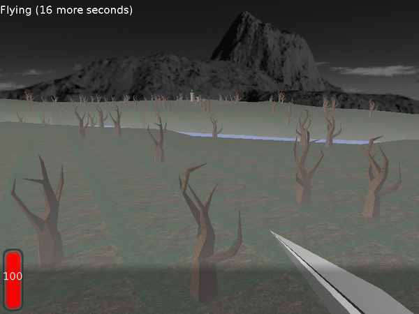
Note that for some features, the caching cannot
be as efficient. This includes things like Attributes.OnBeforeVertex
and the volumetric fog. In these cases, two shapes must have equal transformation
to look exactly the same. So in these cases (this is automatically
detected by the engine) we have a little less sharing,
and use more memory.
For example, look at these two trees on a scene that uses the blue volumetric fog.
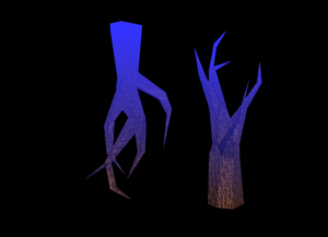
Figure 6.3. The wrong rendering of the trees with volumetric fog, if we would use the same arrays/VBO (containing fog coordinate for each vertex) for both trees.
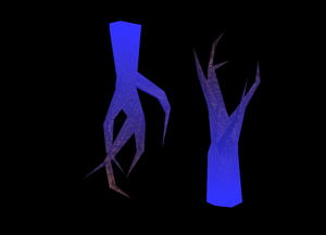
TGLRenderer class does
the basic OpenGL rendering of VRML nodes.
“Basic” rendering means that this class is not supposed to
choose the order of rendering of VRML nodes.
This implicates that TGLRenderer is
not responsible for doing optimizations that
pick only some subset of VRML nodes for rendering
(for example, only the nodes visible within the camera frustum).
This also implicates that it's not responsible for arranging
the rendering order for OpenGL blending, see
Section 6.4.1, “Material transparency using OpenGL alpha blending”.
In fact, it doesn't set any OpenGL blending parameters
(aside from setting colors alpha values as appropriate).
This limitation is done by design. A higher-level routines will internally use an instance of this class to perform rendering. These higher-level routines should choose in what shapes to render, and in which order. In the next Section 6.4, “VRML scene class for OpenGL” we will get familiar with such higher-level class.
The way to use TGLRenderer looks
like this:
First you must call
Preparemethod for all theStateinstances that you want to later use for rendering. You can obtain suchStateinstances for example by a traverse callback discussed earlier in Section 3.6, “Traversing VRML graph”. The order of callingPreparemethods doesn't matter — it's only important for you to prepare all states before you will render them.For example
Preparecalls may load textures into OpenGL, and triangulate outline fonts (used by VRMLTextandAsciiTextnodes).You are free to mix
Preparecalls with any other rendering calls to OpenGL. This doesn't matter, asPrepareonly prepares some resources, without changing OpenGL state. You cannot delete yourself any resources (texture names, display lists, buffer objects etc.) reserved insidePreparecalls. A properly written OpenGL program should always allocate free resource names using calls likeglGenTexturesanyway.Call
RenderBeginto start actual rendering. This will set up some OpenGL state that will be assumed by further rendering calls.If
Attributes.PreserveOpenGLState, this also does a push of OpenGL attributes stack, so that everything can be restored later byRenderEnd. Unfortunately, this is quite costly operation, and it's often not needed (when you don't do any custom OpenGL rendering), soAttributes.PreserveOpenGLStateis false by default.Then you should call
RenderShapefor each VRML/X3D shape that you want to render. As mentioned earlier, all the shapes have to be previously prepared by aPreparecall.Finally after you rendered all your shapes, you should call
RenderEnd.Between
RenderBeginandRenderEndyou are not allowed to change OpenGL state in any way except for calling otherTGLRenderermethods. Well, actually there are some exceptions, things that you can legitimately do — these include e.g. setting enabled state of OpenGL blending. But generally you should limit yourself to calling otherTGLRenderermethods betweenRenderBeginandRenderEnd.
Of course the scenario above may be repeated as many times as you want.
The key is that you will not have to repeat Prepare
calls each time — once a state is prepared, you can use it in
RenderShape calls as many times as you want.
If you will not need some state anymore then you can release some
resources allocated by it's Prepare call
by using UnPrepare or UnPrepareAll
methods.
Note that TGLRenderer
doesn't try to control whole OpenGL state. It controls only the state
that it needs to, to accurately render VRML nodes. Some OpenGL
settings that are not controlled include:
global ambient light value (
glLightModelwithGL_LIGHT_MODEL_AMBIENTparameter),polygon mode (filled or wireframe?),
blending settings.
So you can adjust some rendering properties simply by
using normal OpenGL commands. Also you can transform rendered
VRML models simply by setting appropriate modelview matrix
before calling RenderBegin. So rendering
done by TGLRenderer tries to cooperate
with OpenGL nicely, acting just like a “complex
OpenGL operation”, that plays nicely when mixed with other OpenGL
operations.
However, for various implementation reasons, many other
VRML rendering properties cannot be controlled by just setting
OpenGL state before using RenderBegin.
Instead you can adjust them by setting Attributes
property of TGLRenderer.
Often when you render various VRML models, you will
use various TGLRenderer instances. But still
you want those TGLRenderer instances
to share some common resources. For example, each texture has to
be loaded into OpenGL context only once. It would be ridiculous
to load the same texture as many times as there are VRML models
using it. That's why we have TGLRendererContextCache.
It can be used by various renderers to store common resources,
like an OpenGL texture name associated with given texture filename.
Things that are cached include:
Fonts display lists.
Texture names. This way you can make your whole OpenGL context to share common “texture pool” — and all you have to do is to pass the same
TGLRendererContextCacheinstance around.Shape information: arrays and VBOs mentioned in previous chapter.
By default, each TGLRenderer creates and uses his own
cache, but you can create TGLRendererContextCache
instance explicitly and just pass it down to every OpenGL renderer that
you will create. All higher-level objects that use TGLRenderer
renderer allow you to pass your desired TGLRendererContextCache.
And you should use it, if you want to seriously conserve memory
usage of your program.
Also note that when animating, all animation frames of given animation
object (TCastlePrecalculatedAnimation instance, that will be described
in details in Chapter 7, Animation) always use the same
renderer. So they also always use the same cache instance, which already
gives you some memory savings thanks to cache automatically.
Historically, we used to have many rendering routines for various nodes.
This turned out to be extremely cumbersome to maintain.
The new "geometry arrays" approach unifies this, translating every
shape to only a couple of primitives that map nicely to OpenGL
(triangles, quads, quad strips etc.).
The "geometry arrays" are also be used to implement
TShape.LocalTriangulate and
TShape.Triangulate.
Thus, rendering and triangulating is nicely unified.
We also have an alternative, debugging renderer that
will be used if you define USE_VRML_TRIANGULATION
symbol for compilation of GLRenderer
unit. Each node will be triangulated
using TShape.LocalTriangulate method
(mentioned earlier in Section 3.7.2, “Triangulating”)
and each triangle will be passed to OpenGL. This is a very limited rendering
method, only to show that TShape.LocalTriangulate
works correctly:
It's slower than normal rendering through arrays and VBOs.
Things that are not expressed as triangles (
IndexedLineSet,PointSet) will not be rendered at all.It lacks some features, because the triangulating routines do not return enough information. For example, only the first texture unit gets correct texture coordinates, so multi-texturing doesn't work (correctly).
TCastleScene is a descendant of
TCastleSceneCore (which was introduced earlier in
Section 3.10, “VRML scene”). Internally it uses
TGLRenderer (introduced in last section,
Section 6.3, “Basic OpenGL rendering”) to render scene
to OpenGL. It also provides higher-level optimizations and features for
OpenGL rendering. In short, this is the most comfortable
and complete class that you should use to load and render static
VRML models. In addition to TCastleSceneCore features,
it allows you to:
Render all shapes (i.e. whole VRML scene). Use
Rendermethod withnilasTestShapeVisibilityparameter for the simplest rendering method.You can render only the shapes that are within current camera frustum by
RenderFrustum. This works by checking each shape for collision with frustum before rendering. Generally, it makes a great rendering optimization if user doesn't usually see the whole scene at once.When you initialize shape octree for rendering, by adding
ssRenderingtoTCastleScene.Spatial, thenRenderFrustumwill work even better. The shapes within the frustum will be determined by traversing the shape octree. If your scene has many shapes then this will be faster than without octree.In special cases you may be able to create a specialized test whether given shape is visible. You can call
Rendermethod passing as a parameter pointer to your specialized test routine. This way you may be able to add some special optimizations in particular cases.For example if you know that the scene uses a dense fog and it has a matching background color (for example by
BackgroundVRML node) then it's sensible to ignore shapes that are further then fog's visibility range. In other words, you only draw shapes within a sphere around the player position.A working example program that uses exactly this approach is available in our engine sources in the file
castle_game_engine/examples/vrml/fog_culling.lpr.On the screenshot below the fog is turned off. Camera frustum culling is used to optimize rendering, and so only 297 spheres out of all 866 spheres on the scene need to be rendered.
On the next screenshot the fog is turned on. The same view is rendered. We render only the objects within fog visibility range, and easily achieve a drastic improvement: only 65 spheres are passed to OpenGL now. Actually we could improve this result even more: in this case, both camera frustum culling and culling to the fog range could be used. Screenshot suggests that only 9 spheres would be rendered then.
Figure 6.5. Rendering with the fog (only objects within the fog visibility range need to be rendered)
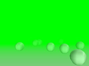
TCastleSceneimplements material transparency by OpenGL alpha blending. This requires rearranging the order in which shapes are rendered, that's why it must be done in this class (instead of being done insideTGLRenderer).Details about this will be revealed soon in Section 6.4.1, “Material transparency using OpenGL alpha blending”.
TCastleScenehas also comfortable methods to handle and render VRMLBackgroundnode of your scene.
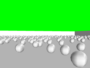
To understand the issue you have to understand how OpenGL
works. OpenGL doesn't “remember” all the triangles sent to it.
As soon as you finish passing a triangle to OpenGL (which means
making glVertex call that completes the triangle)
OpenGL implementation is free to immediately render it.
This means mapping the given triangle to 2D window and updating data
in various buffers — most notably the color buffer, but also
the depth buffer, the stencil buffer and possibly others.
Right after triangle is rendered this way, OpenGL implementation
can completely “forget” about the fact that it just
rendered the triangle. All triangle geometry, materials etc.
information doesn't have to be kept anywhere. The only trace
after rendering the triangle is left in the buffers (but these
are large 2D arrays of data, and only the human eye can reconstruct
the geometry of the triangle by looking at the color buffer contents).
In summary, this means that the order in which you pass the triangles to OpenGL is significant. Rendering opaque objects with the help of depth buffer is the particular and simple case when this order doesn't matter (aside for issues related to depth buffer inaccuracy or overlapping geometry). But generally the order matters. Using alpha blending is one such case.
To implement VRML material transparency we use materials with alpha (4th color component) set to value lower than 1.0. When the triangle is specified, OpenGL renders it. A special operation mode is done for updating color buffer: instead of overriding old color values, the new and old colors are mixed, taking into account alpha (which acts as opacity factor here) value. Of course when rendering transparent triangles they still must be tested versus depth buffer, that contains at this point information about all the triangles rendered so far within this frame.
Now observe that depth buffer should not be updated as a result of rendering partially transparent triangle. Reason: partially transparent triangle doesn't hide the geometry behind it. If we will happen to render later other triangle (partially transparent or opaque) behind current partially transparent triangle, then the future triangle should not be eliminated by the current triangle. So only rendering opaque objects can change depth buffer data, and thus opaque objects hide all (partially transparent or opaque) objects behind them.
But what will happen now if you render opaque triangle that is behind already rendered partially transparent triangle? The opaque triangle will cover the partially transparent one, because the information about partially transparent triangle was not recorded in depth buffer. For example you will get this incorrect result:
Figure 6.6. The ghost creature on this screenshot is actually very close to the player. But it's transparent and is rendered incorrectly: gets covered by the ground and trees.
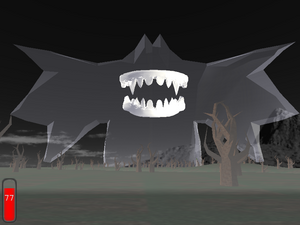
The solution is to avoid this situation and render all partially transparent objects after all opaque objects. This will give correct result, like this:
Figure 6.7. The transparent ghost rendered correctly: you can see that it's floating right before the player.
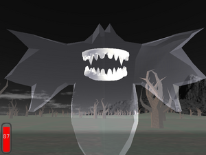
Actually, in a general situation, rendering all partially
transparent objects after opaque objects is not enough.
That's because if more than one transparent object is visible on the
same screen pixel, then the order in which they are rendered matters —
because they are blended with color buffer in the same order as they
are passed to OpenGL. For example if you set your blending functions
to standard (GL_SRC_ALPHA,
GL_ONE_MINUS_SRC_ALPHA) then each time
you render a triangle with color (Red, Green, Blue) and opacity α,
the current screen pixel color (ScreenRed,
ScreenGreen, ScreenBlue)
changes to
(ScreenRed, ScreenGreen, ScreenBlue) * (1 - α) + (Red, Green, Blue) * α
Consider for example two partially transparent triangles, one of them red and the second one green, both with α set to 0.9. Suppose that they are both visible on the same pixel. If you render the red triangle first, then the pixel color will be
ScreenColor * (1 - α) * (1 - α) +
RedColor * α * (1 - α) + GreenColor * α =
ScreenColor * 0.01 + RedColor * 0.09 + GreenColor * 0.9 =
visible as GreenColor in practice
If you render green triangle first then the analogous calculations will get you pixel color close to the red.
So the more correct solution to this problem is to sort your transparent
triangles with respect to their distance from the viewer.
You should render first the objects that are more distant.
Since April 2009 you can activate sorting shapes of transparent
objects by setting Attributes.BlendingSort := true.
However, this solution isn't really perfect. Sorting shapes is only an approximation, in more general case you should sort single triangles. Sorting all triangles at each frame (or after each camera move) doesn't seem like a good idea for a 3D simulation that must be done in real-time as fast as possible. Moreover, there are pathological cases when even sorting triangles is not enough and you will have to split triangles to get things 100% right. So it's just not possible to overcome the problem without effectively sorting at each screen pixel separately, which is not doable without hardware help.
That's why our engine by default just ignores the order problem
(Attributes.BlendingSort is false
by default). We do not
pay any attention to the order of rendering of transparent
objects — as long as they are rendered after all opaque objects.
In practice, rendering artifacts will occur only in some complex combinations of
transparent objects. If you seldom use a transparent object,
then you have small chance of ever hitting the situation that actually
requires you to sort the triangles. Moreover, even in these situations,
the rendering artifacts are usually not noticeable to casual user. Fast real-time
rendering is far more important that 100% accuracy here.
Moreover, our engine right now by default uses
(GL_SRC_ALPHA, GL_ONE)
blending functions, which means that the resulting pixel color
is calculated as
(ScreenRed, ScreenGreen, ScreenBlue) + (Red, Green, Blue) * α
That is, the current screen color is not scaled by (1 - α).
We only add new color, scaled by it's alpha. This way rendering
order of the transparent triangles doesn't matter — any order will
produce the same results. For some uses
(GL_SRC_ALPHA, GL_ONE)
functions look better than (GL_SRC_ALPHA,
GL_ONE_MINUS_SRC_ALPHA), for some uses they are worse.
(GL_SRC_ALPHA, GL_ONE) tend
to make image too bright (since transparent objects only increase the
color values), that's actually good as long as your transparent objects
represent some bright-colored and dense objects (a thick plastic glass,
for example). (GL_SRC_ALPHA,
GL_ONE_MINUS_SRC_ALPHA) on the other hand can
sometimes unnaturally darken the opaque objects behind (since that's
what these functions will do for a dark transparent object with large alpha).
Other method of rendering material transparency deserves a quick note here. It's done by polygon stipple, which means that transparent triangles are rendered using special bit mask. This way part of their pixels are rendered as opaque, and part of them are not rendered at all. This creates a transparent look on sufficiently large resolution. Order of rendering transparent objects doesn't matter in this case.
However, the practical disadvantages of this method is that it looks quite, well, ugly. When we use random stipples (to precisely show different transparency of different objects) then the random stipples look very ugly:
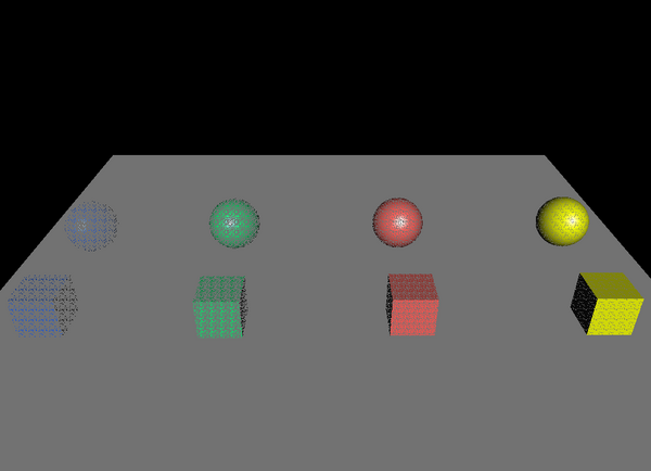
Instead of using random stipples, we can use a couple of special good-looking prepared regular stipples. But then we don't have much ability to accurately represent various transparency values (especially for very transparent objects). And still the results look quite bad:
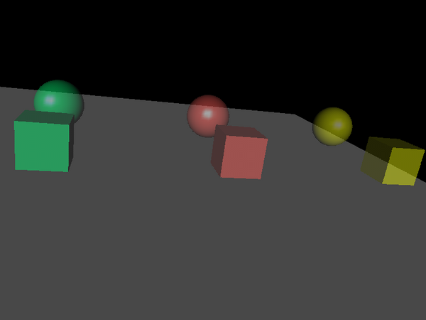
Optimizations done by TCastleScene
(in particular, frustum culling) work best when the scene
is sensibly divided into a number of small shapes.
This means that “internal” design of VRML model (how it's
divided into shapes) matters a lot. Here are some guidelines for
VRML authors:
Don't define your entire world model as one
IndexedFaceSetnode, as this makes frustum culling compare frustum only with bounding box of the whole scene. Unless your scene is usually visible completely / not visible at all on the screen, in which case this is actually a good idea.Avoid
IndexedFaceSetnodes with triangles that are scattered all around the whole scene. Such nodes will have very large bounding box and will be judged as visible from almost every camera position in the scene, thus making optimizations like frustum culling less efficient.An ideal VRML model is split into many shapes that have small bounding boxes. It's hard to specify a precise “optimal” number of shapes, so you should just test your VRML model as much as you can. Generally,
RenderFrustumwithssRenderingoctree should be able to handle efficiently even models with a lot of shapes.
Then comes an idea to use scene division into triangles instead of shapes. This would mean that our optimization doesn't depend on shape division so much. Large shapes would no longer be a problematic case.
To make this work we would have to traverse triangle octree to decide which triangles are in the visibility frustum. Doing this without the octree, i.e. testing each triangle against the frustum, would be pointless, since this is what OpenGL already does by itself.
Such traversing of the octree would have to be the first pass, used only to mark visible triangles. In the second pass we would take each shape and render marked triangles from it. The reason for this two-pass approach is that otherwise (if we would try to render triangles immediately when traversing the octree) we would produce too much overhead for OpenGL. Overhead would come from changing material/texture/etc. properties very often, since we would probably find triangles from various nodes (with various properties) very close in some octree leafs.
But this approach creates problems:
The rendering routines would have to be written much more intelligently to avoid rendering unmarked triangles. This is not as easy as it seems as it collides with some smart tricks to improve vertex sharing, like using OpenGL primitives (
GL_QUAD_STRIPetc.).We would be unable to put large parts of rendering pipeline into OpenGL arrays. Constructing separate VBO for each triangle has little sense.
That's why this approach is not implemented.
Table of Contents
There are two approaches to playing a 3D animation in our engine.
They both use TCastleScene for playback,
start the animation by calling TCastleScene.PlayAnimation
or setting TCastleScene.AutoAnimation.
This approach means that you load one model file, and the
TCastleScene (actually, ancestor
TCastleSceneCore)
will make the events work, sending/receiving events through routes,
activating sensors, running scripts etc. Among many things,
this means that world time will be passed to TimeSensor nodes,
allowing you to animate by interpolator nodes.
You can also pass user input to TCastleSceneCore
methods like TCastleSceneCore.KeyDown,
and then the user will be able to fully interact with the VRML scene.
This is what should be used for presenting interactive X3D / VRML world to the user, as envisioned by X3D / VRML specifications.
This approach means that at loading time we "fix" the whole the animation. Animation becomes something like a 3D movie.
A downside is that loading time (and other resources usage, like memory) is larger, especially for longer animations. That's because we store the whole animation in memory.
Huge advantage of this method: once loaded, animation can be played ultra-fast. Actually, it's as fast a displaying a still model (currently, this is exactly what is done under the hood: at each time, we simply display one chosen frame of animation; in the future this may change, but still will be lighting fast). That's the reward for long loading time and "fixing" the animation.
We generally do not recommend this method anymore.
castle-anim-frames (Castle Game Engine animations) format was specifically created to describe precalculated animations.
We also load MD3 (Quake3 engine) animations to this form, as they are especially suitable for it.
TNodeInterpolator class is used to build
and render precalculated animations.
For each provided frame we have an associated time.
The resulting animation will change the first model to the last one,
such that at any time point we will either use one of the predefined models
(if point in time is close to the model's associated time) or a new
model created by interpolating between two successive models in time.
Under the hood, we have quite intelligent algorithm that checks
each pair of two successive models for structural equality.
“Structural equality” simply means that the two models
are equal, with the exception of various floating-point fields,
on which they may differ. The idea is that we can define linear
interpolation between two models that are structurally equal.
So when you specify two structurally equal models for an animation,
we can generate many intermediate scenes (this is
the ScenesPerTime
parameter to loading method) that smoothly show one model changing into
the other. This can interpolate any floating-point field value, like
SFColor,
SFFloat, SFMatrix,
SFRotation, SFVec2f and
SFVec3f an all equivalent multi-valued fields
(they can differ in values, but still must have the same number of items).
For example, the first model may be a small sphere with blue color, and the second model may be a larger sphere with white color. The resulting animation depicts a growing sphere with color fading from blue to white. More examples:
Moving, rotating, scaling objects may be expressed by changing transformation values.
Any kind of morphing (mesh deformation) may be expressed by changing values of
IndexedFaceSetcoordinates.Materials, colors, lights may change. Even such properties like a material transparency, or a light position or direction.
Texture coordinates may change to achieve effects like a moving water surface.
Another advantage of structural equality is that we will perform aggressive merging of two structurally equal models. This means that when two nodes are detected to be exactly equal, one of them will be removed (and pointers rearranged to both point to the same node in memory). If the nodes are not exactly equal, we still check their children and possibly merge them. This is a huge saving in terms of memory, as practically all the non-animated parts of the model will only be kept once in memory. It's implemented quite intelligently, so it's actually a relatively fast process done during the model loading.
All the models of the animation do not actually have to be structurally equal. You can even change one model into something completely different. But in these cases we cannot generate smooth transition from one model to the other, and the animation will just show a sudden change into new version at it's time.
If you're concerned that possibly some parts of your animation
are not structurally equal, you can always load them into
view3dscene
run with --debug-log command-line option.
Then, at loading time, you will get messages on console if two
successive models were not detected as structurally equal
(and so a sharp change from one to the other will be shown in animation).
The message will also describe exactly where the difference is found.
First of all, the scenes are not interpolated when
rendering. Instead, at loading time, we create
a number of new interpolated models and save them
(along with the models that were specified explicitly).
The parameter ScenesPerTime
says with what granularity the intermediate scenes
are constructed for a time unit.
If you specify too large
ScenesPerTime your animations will take a lot
of time to prepare and will require a lot of memory.
On the other hand too small ScenesPerTime value will
result in an unpleasant jagged animation. Ideally, ScenesPerTime
should be >= than the number of frames you will render in your time unit,
but this is usually way too large value.
Special value of 0 for ScenesPerTime
means that you want only the explicitly passed nodes in the scene,
nothing more. No more intermediate scenes will ever be created.
This creates a trivial animation that suddenly jumps from
one still model to the next at specified times. It may be useful if you
already have generated a lot of models, densely distributed
over time, and you don't need TNodeInterpolator to insert any more
scenes. Structural equality (or it's lack)
doesn't change the look of such animation, as no additional interpolation is done
when loading, but still structurally equal models may be merged
to conserve memory use.
Internally, the TNodeInterpolator wraps
each model (that was specified explicitly or created by interpolation)
in a new node.
This means that we have all the features
of our static OpenGL rendering available when doing animations too.
We have a special file format to express precalculated animations: castle-anim-frames, Castle Game Engine animations. It references a number of static 3D model files and their corresponding times, describing the animation.
If you want to experiment with castle-anim-frames format,
view3dscene
can load and play animations in castle-anim-frames format.
You can find example castle-anim-frames animations in
VRML/X3D demo models
(see directory castle-anim-frames/),
the sources of our engine also contain simple examples in
directory castle_game_engine/examples/
(like resource_animations that plays animations
specified in resource.xml files for game creatures/items).
Also “The
Castle” uses such animations for all creatures and weapons.
In general, using a single glTF, X3D, VRML, Spine file is a much better approach than castle-anim-frames files.
Also, castle-anim-frames files may waste a lot of disk space if your animation tries to change two pieces of your model with drastically different speeds. Consider this:
It's OK to create an animation with a box that blinks (changes color) 100 times per time unit. Just 2 model files are needed for this, with castle-anim-frames file specifying to loop them over a short period of time.
It's also OK to create an animation with a sphere that blinks only once for a given time unit.
But if you want to create an animation that contains both the box (blinking 100 times/time unit) and the sphere (blinking once for a time unit), you will have to prepare 100 still 3D files to express this!
VRML interpolators don't have this problem, since every interpolator has it's own set of keys. So both can be placed within the same file, without the need to explicitly write 100 values anywhere.
Despite this, there remains one practical advantage of using castle-anim-frames file format: you can design your animations using any authoring software that can export static VRML files. If your modeler can design animations, but doesn't save them to VRML interpolator nodes, all you have to do is to export your models a couple of times from a couple of different points in time.
In the old days, this allowed us to use Blender do design animations and export them. Nowadays, we export from Blender to glTF using standard Blender exporter, and there's no need for castle-anim-frames.
Table of Contents
You can easily render shadow volume for any TCastleScene
by TCastleScene.RenderShadowVolume method.
Some features (see any article about shadow volumes to know what they mean) :
Silhouette edge detection is done, of course the model must be 2-manifold for this to work.
ManifoldEdges structure is prepared once during pre-processing step (by
PrepareRendercall withprShadowVolume, or simply on first call toRenderShadowVolume). This allows rendering shadow quads with silhouette detection in O(n+m) time, where n is a number of edges and m is a number of triangles (these are roughly equal since on a perfect 2-manifold 3 * m = 2 * n). Without calculated ManifoldEdges, this would have to take square time, O(m2).To account also models that are not completely 2-manifold, we have BorderEdges list with edges that have only one neighbor triangle. Actually, it lists edges with any odd number of neighbors (each neighbor pair makes one edge in ManifoldEdges, and then one left neighbor makes one BorderEdges item). All BorderEdges are always considered part of the silhouette. This is not a perfect solution, further in this chapter I present when this fails. When it fails, there are two solutions:
fix the model to be 2-manifold.
or use the much slower algorithm version that doesn't do silhouette edge detection.
Both Z-pass and Z-fail approaches are done. We automatically detect when Z-fail is needed, and in 99% of the cases we can use faster Z-pass approach.
Both positional and directional lights are supported.
Using homogeneous coordinates tricks: we render shadow quads vertexes in real infinity, and we can use perspective projection that has no far clipping plane.
We do shadow volume culling for scenes (that is, we try to avoid rendering shadow quads when it's obvious the scene shadow can't be visible within current camera frustum). Implemented in
TGLShadowVolumeRenderer.InitScene. It's not fully implemented, we could take more conservative convex hull between light position and frustum. But it seems that this wouldn't improve culling significantly, current approach gives us almost as much as we can get from frustum culling.More drastic improvements can only come from the use of portals.
Actually, our TCastleSceneManager does pretty much
everything for you. Just set ShadowVolumesPossible and
ShadowVolumes to true.
That's it — we will take care to render with shadow volumes.
You can change
ShadowVolumesdynamically during the game (for example, if user changes video preferences).ShadowVolumesPossibleshould remain constant and reflect whether we have stencil buffer available. Dynamically changingShadowVolumesPossibleis actually allowed, but it may cause costly recalculation once the models are actually loaded. Also, projection may need to be reapplied (only whenShadowVolumesPossible, we force infinite far plane, which is needed for z-fail, when camera near plane is inside the shadow volume).
You should also take care to initialize OpenGL context requiring
stencil buffer (8-bit should be enough for practical uses).
This is something that has to be requested outside of scene manager.
The simplest way to do this is to use TCastleWindow.OpenOptionalMultiSamplingAndStencil
method instead of TCastleWindow.Open,
see examples/vrml/simplest_vrml_browser_with_shadow_volumes.lpr.
To actually define what lights are used for shadow volumes,
set shadowVolumes and shadowVolumesMain
to true on some VRML/X3D light node. See https://castle-engine.io/x3d_extensions.php#section_ext_shadows
for details. Alternatively, you can control the main light source
by overriding TCastleSceneManager.MainLightForShadows.
If you define your own T3D descendant,
be sure to override T3D.RenderShadowVolume method.
See API reference for details now to handle it.
You can change ReceiveShadowVolumes
and CastShadowVolumes properties of every
T3D descendant.
The whole approach is quite flexible and is used throughout my whole engine, and it will use all implemented shadow volume optimizations under the hood. For example, see "The Castle" game, where almost everything may have a shadow rendered by shadow volumes — creatures, level scene, level objects. And everything goes through this same approach, getting all optimizations.
You can see how silhouette edge detection goes, which
edges from ManifoldEdges (2 neighbors) are qualified as silhouette and
which edges were detected as BorderEdges. This is available in
view3dscene
by View -> Fill mode -> Silhouette and Border Edges
menu item.
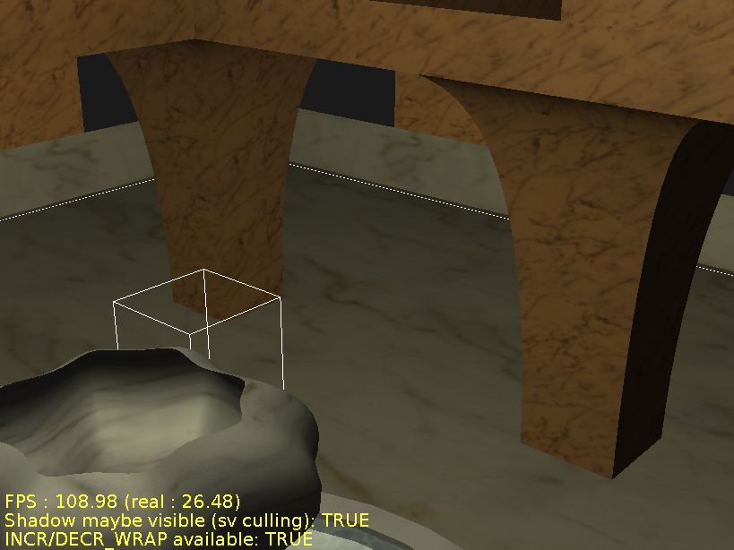
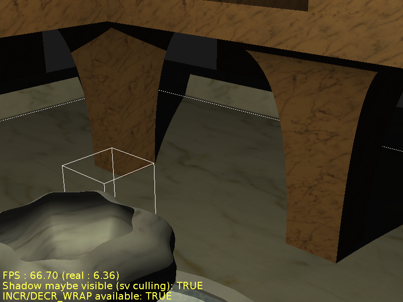
Now, turn edges on. Silhouette edges detected are drawn yellow (these depend on light position relative to the model). Blue edges are BorderEdges (these are independent from light position, they are simply edges with only 1 neighbor triangle).
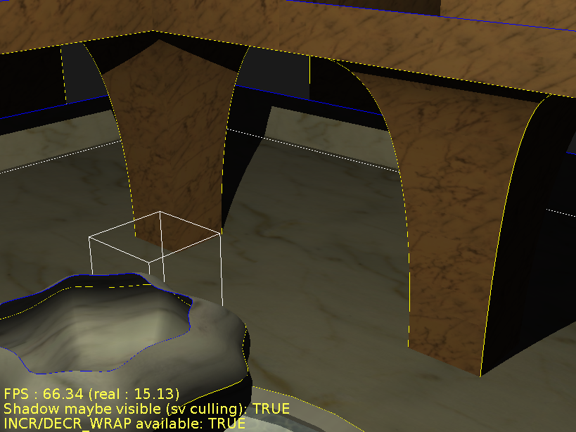
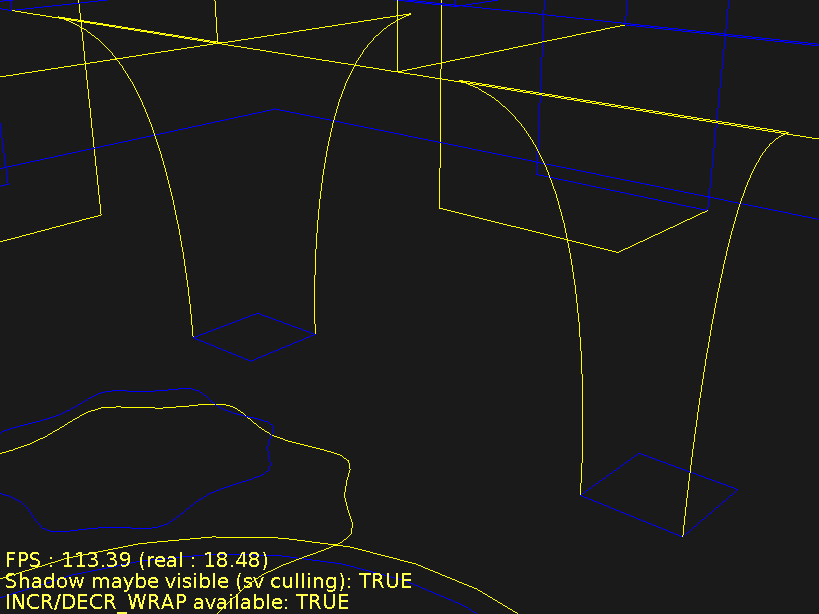
Well known, practically unavoidable problem with shadow volume algorithm are ghost shadows. See example below:
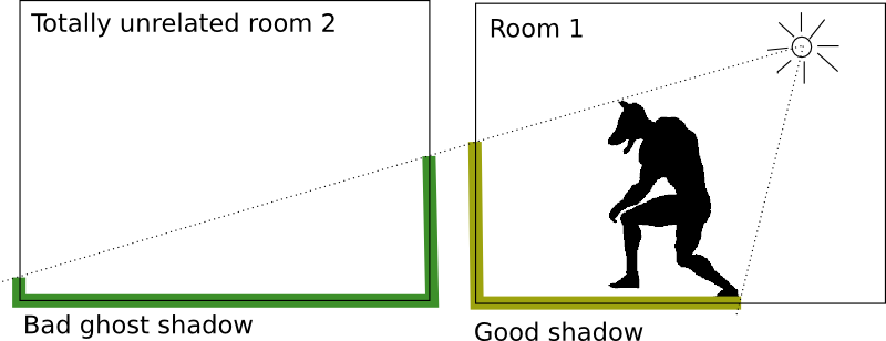
This is practically unavoidable, since to fix this, you would have to cap shadow quads where the room 1 ends. This is very computationally intensive task (for real-time graphics at least), since you must calculate the common part of two 3D objects.
Using BorderEdges idea, to force silhouette edge detection even with non-2-manifold models, can cause artifacts for similar reasons as "ghost shadows". But in this case, the effect is that not enough of the area is covered by shadow (as opposed by normal ghost shadows artifacts that cause too much area to be covered by shadow). This artifacts are similarly unavoidable, on the same reasoning.
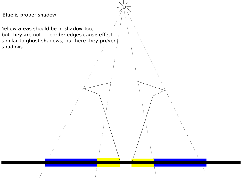
Yet another problem related to BorderEdges is the fact that silhouettes may be not closed properly. Why? Because part of the silhouette goes on the border edges. To make silhouettes closed, we would have to render shadow quads for some border edges twice (or not at all), yet I'm not sure for now how can I do this easily.
Illustrated example why and when this problem occurs is below. Consider a cylinder capped at the top and open at the bottom.
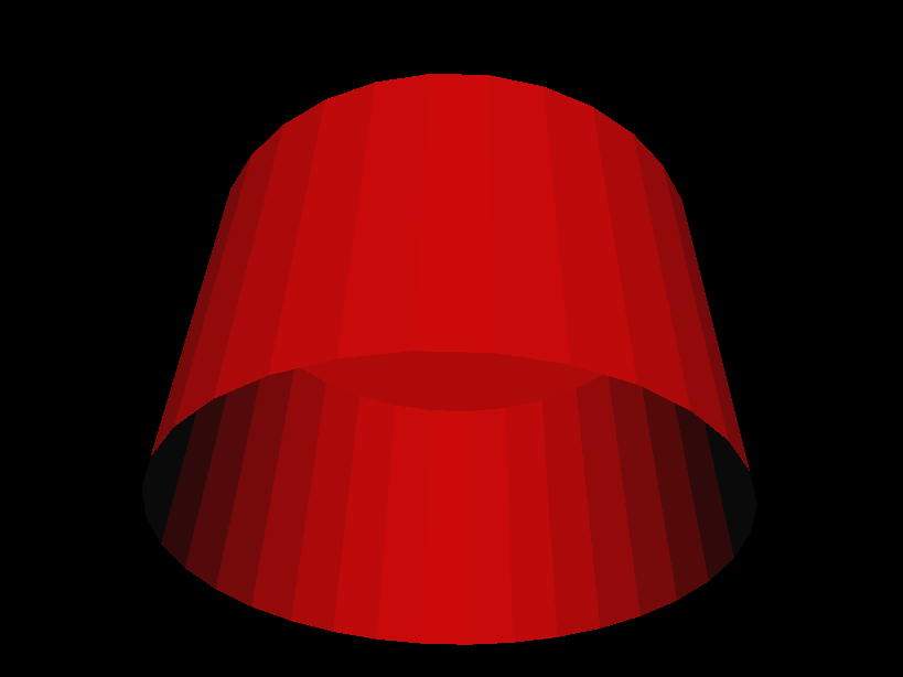
Now assume a positional light above this cylinder. The light is above, but not precisely above — that is, the light lights the top and some sides of the cylinder. Image below shows generated shadows quads, silhouette (yellow) edges and border (blue) edges.
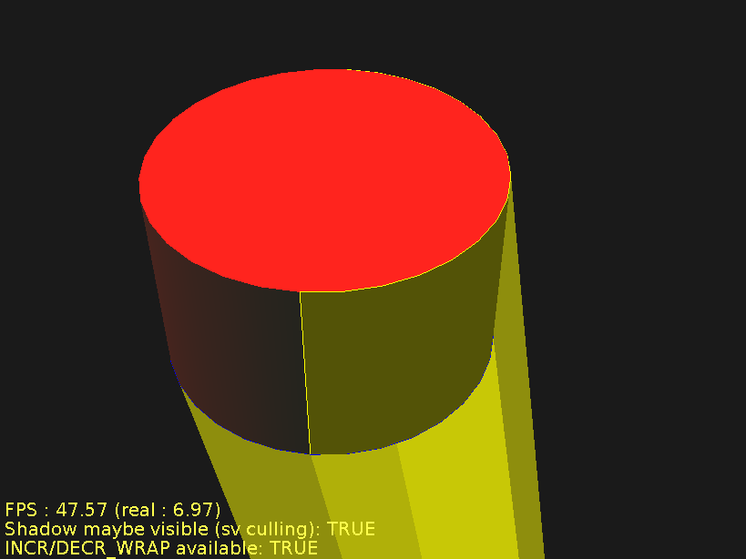
The last image shows the same thing as above, but the cylinder geometry is not rendered, to make things clear. You should be able to see what's going wrong here: part of the blue (border) edges should be part of the silhouette too. The blue edges on the right side should either produce two shadow quads, or none at all. Otherwise the shadow volume is not correctly closed, and the shadows appear on completely wrong places of the screen.
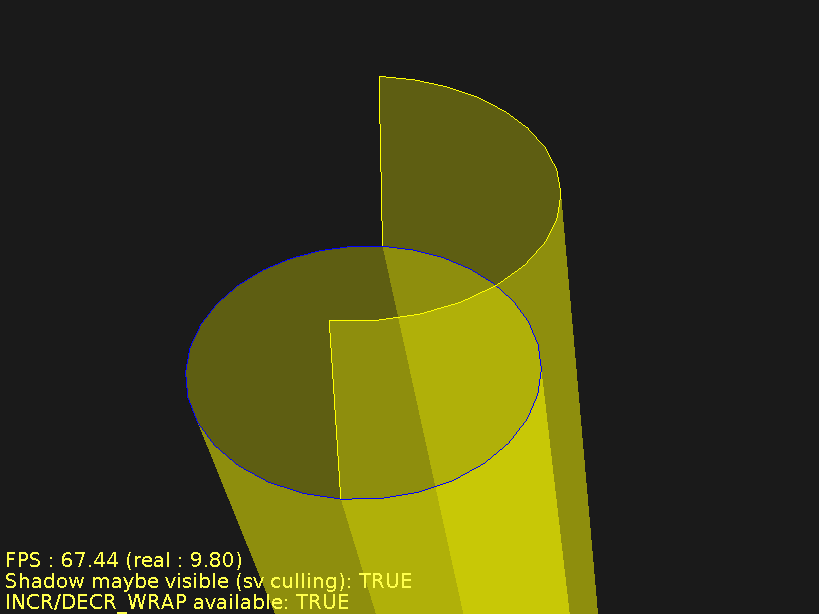
Solution, as usual for BorderEdges problems, is to avoid them: make your models truly 2-manifold, or use slower version of algorithm without silhouette edge detection.
Another artifact is painfully visible when rendering such models using z-fail method (used when camera is inside shadow volume). Z-fail requires that shadows volume is capped, i.e. we have to render light cap (triangles facing light, on shadow caster position) and dark cap (triangles facing light, extruded to infinity). But in case of non-2-manifold models, triangles facing light may not cap the volume fully. In fact, for non-2-manifold models, it's possible that no triangles will face the light — even when shadow volume exists !
Below we see screenshots of triangle.x3dv
test (see engine demo models, shadow_volumes dir).
All screenshors were done with z-fail method forced.
The shadow caster in this case is a simple single triangle.
It's not 2-manifold, it has 3 BorderEdges.
The first screenshot shows the correct result: triangle correctly
shadows the environment. Second screenshot shows the same scene
with shadow volumes drawn, so that we can see what's going on.
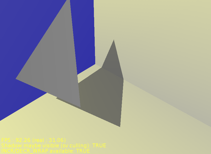
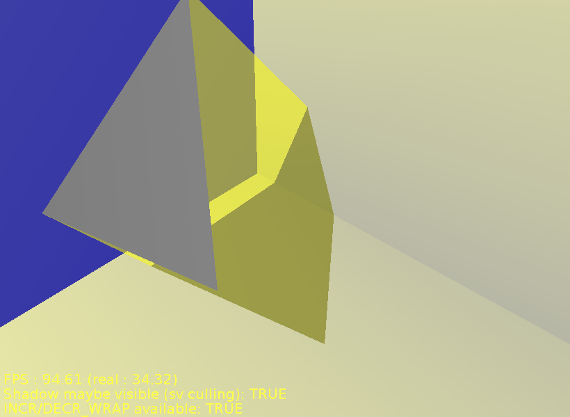
Now, what happens if we simply rotate the triangle, so that the other side of it is visible? The situation seems completely analogous, so we would expect to see the same effect... But we don't.
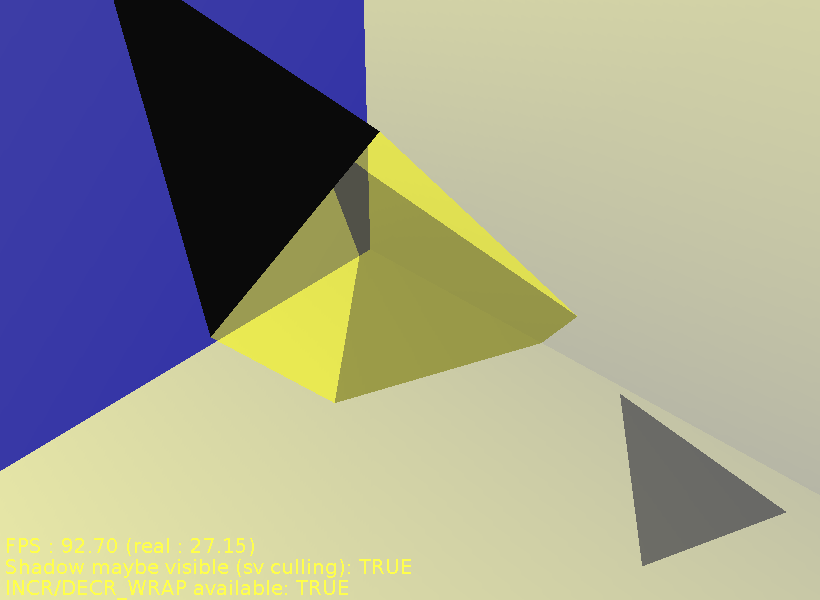
We see that triangle is incorrectly in it's own shadow, and we see another strange shadow of the triangle. What happened here? These are both the effects of lacking the caps for z-fail method:
Lack of light cap means that triangle is considered in it's own shadow. In fact, anything between the triangle and the camera (regardless of light position !) would be considered in shadow, because the shadow cap is "open" there.
Lack of dark cap means that somewhere in infinity there's a place where one front facing shadow quad is visible, but no back facing shadow quads. This means that value in stencil buffer is -1, so it's not zero, so the pixels are considered in shadow.
Now, why both the caps are lacking? Because there are no triangles in the model that are front-facing to the light. In this simple scene, there's only one triangle: when it's front-facing to the light, we're lucky and things work fine, but when it's back-facing to the light, errors occur.
Table of Contents
Our VRML / X3D engine homepage, including:
Engine documentation — the document that you're reading right now
view3dscene — VRML (1.0, 2.0), X3D browser, and a viewer for other 3D formats (3DS, OBJ, Collada, MD3, others)
overview and sources of my engine and their reference
See also author's private homepage.
Version of this document
This documentation started it's life as my master's thesis, under the title VRML processing and rendering engine, and under the supervision of dr Andrzej Łukaszewski. It was submitted and passed in September 2006 by the Institute of Computer Science at University of Wrocław in Poland. If you're curious, you can find this old version at http://www.ii.uni.wroc.pl/~anl/MGR/.
Our engine evolved quite a lot since that time, and so this documentation was heavily updated and extended since then.