Geometry3D component
This component provides the most commonly used 3D objects.
IndexedFaceSet defines a 3D object as a set of polygons,
and is the most often method to render 3D data.
ElevationGrid allows to easily render a heightfield
(like a terrain). Extrusion allows
to render a 3D object by extruding a 2D shape along a 3D spine.
Primitives
Sphere, Box, Cone, Cylinder
provide the well-known simple 3D objects.
Contents:
1. Supported nodes
IndexedFaceSet(Pascal API:TIndexedFaceSetNode)This is the most versatile node to render a mesh. The geometry is defined as a set of polygons. Many fields allow to provide positions, indexes, and various per-vertex information (colors, normal vectors, shader attributes etc.).
Sphere(Pascal API:TSphereNode),
Box(Pascal API:TBoxNode),
Cone(Pascal API:TConeNode),
Cylinder(Pascal API:TCylinderNode)These geometry nodes allow to easily render simple primitives.
Note that by default they are only visible from the outside. You can use the
solidfield to make them visible from the inside too.ElevationGrid(Pascal API:TElevationGridNode)This geometry node represents a regular grid with a different height at each point. It can be used to render height maps, terrains. Check out the engine "terrain" demo, "Wyrd Forest" demo, and the engine unit
CastleTerrainfor an example usage.Extrusion(Pascal API:TExtrusionNode)This geometry node looks like a 2D cross-section extruded along a "spine" constructed from a series of 3D points. Think of a snake, or a human arm or leg, that bends. Think of the Blender's Extrude operation applied repeatedly.
2. Example in Pascal: build a textured rectangle
Below is a complete example how to construct in Pascal a scene with
IndexedFaceSet and helper nodes (Coordinate,
TextureCoordinate, Shape).
{ Build a simplest IndexedFaceSet node (mesh) to display a texture. } uses SysUtils, CastleWindow, CastleScene, CastleViewport, CastleCameras, CastleColors, CastleVectors, CastleFilesUtils, X3DNodes, CastleTransform; function BuildRootNode(const ImageUrl: String): TX3DRootNode; var Shape: TShapeNode; Geometry: TIndexedFaceSetNode; Coordinate: TCoordinateNode; TextureCoordinate: TTextureCoordinateNode; Texture: TImageTextureNode; Width, Height: Integer; begin { Create ImageTexture node (represents the texture from file) } Texture := TImageTextureNode.Create; Texture.SetUrl([ImageUrl]); if Texture.TextureImage = nil then raise Exception.CreateFmt('Image "%s" could not be loaded', [ImageUrl]); { Read the texture size (it is necessary to determine geometry size) } Width := Texture.TextureImage.Width; Height := Texture.TextureImage.Height; { Create Coordinate node (position of quad in 3D) } Coordinate := TCoordinateNode.Create; Coordinate.SetPoint([ Vector3(-Width / 2, -Height / 2, 0), Vector3( Width / 2, -Height / 2, 0), Vector3( Width / 2, Height / 2, 0), Vector3(-Width / 2, Height / 2, 0) ]); { Create TextureCoordinate node (how the image is mapped onto a surface) } TextureCoordinate := TTextureCoordinateNode.Create; TextureCoordinate.SetPoint([ Vector2(0, 0), Vector2(1, 0), Vector2(1, 1), Vector2(0, 1) ]); { Create Shape and IndexedFaceSet node (mesh with coordinates, texture coordinates) } Geometry := TIndexedFaceSetNode.CreateWithShape(Shape); Geometry.Coord := Coordinate; Geometry.TexCoord := TextureCoordinate; Geometry.Solid := false; // to see it from any side Geometry.SetCoordIndex([0, 1, 2, 3]); { Create Appearance (refers to a texture, connects the Texture to Shape) } Shape.Appearance := TAppearanceNode.Create; Shape.Appearance.Texture := Texture; Result := TX3DRootNode.Create; Result.AddChildren(Shape); end; var Window: TCastleWindow; Viewport: TCastleViewport; Scene: TCastleScene; begin Window := TCastleWindow.Create(Application); Window.Open; Viewport := TCastleViewport.Create(Application); Viewport.FullSize := true; Viewport.Camera.Translation := Vector3(0, 0, 100); Window.Controls.InsertFront(Viewport); Viewport.InsertFront(TCastleExamineNavigation.Create(Application)); Scene := TCastleScene.Create(Application); Scene.Load(BuildRootNode('castle-data:/face.png'), true); Scene.PreciseCollisions := true; Viewport.Items.Add(Scene); Application.Run; end.
3. Example in Pascal: build a textured 3D shape
 |
Below is a complete example how to construct in Pascal a scene with
IndexedFaceSet and helper nodes (Coordinate,
TextureCoordinate, Shape, Transform).
The scene also uses orthographic projection, thanks to OrthoViewpoint
node.
(See also other examples: examples/viewport_and_scenes/build_3d_object_by_code, examples/viewport_and_scenes/build_3d_object_by_code_2_tunnel).
{ Test of orthographic projection (OrthoViewpoint node) showing a few copies of a special mesh (that looks a bit like a box, but with back side shifted). } uses SysUtils, CastleWindow, CastleScene, CastleViewport, CastleCameras, CastleColors, CastleVectors, CastleFilesUtils, X3DNodes, CastleTransform; procedure AddTexturedShearedCube( const RootNode: TX3DRootNode; const Translation: TVector3); const BackFaceShift: TVector2 = (X: 0.5; Y: 0.5); var Faces: TIndexedFaceSetNode; Shape: TShapeNode; Transform: TTransformNode; Coordinate: TCoordinateNode; TextureCoordinate: TTextureCoordinateNode; Texture: TImageTextureNode; begin Coordinate := TCoordinateNode.Create; Coordinate.SetPoint([ Vector3(-1, -1, 1), Vector3( 1, -1, 1), Vector3( 1, 1, 1), Vector3(-1, 1, 1), Vector3(-1 + BackFaceShift.X, -1 + BackFaceShift.Y, -1), Vector3( 1 + BackFaceShift.X, -1 + BackFaceShift.Y, -1), Vector3( 1 + BackFaceShift.X, 1 + BackFaceShift.Y, -1), Vector3(-1 + BackFaceShift.X, 1 + BackFaceShift.Y, -1) ]); TextureCoordinate := TTextureCoordinateNode.Create; TextureCoordinate.SetPoint([ Vector2(0, 0), Vector2(1, 0), Vector2(1, 1), Vector2(0, 1) ]); { This creates TIndexedFaceSetNode, with a TShapeNode that contains it (Shape.Geometry will be set to Faces), with a TTransformNode that contains it (Transform first and only child will be Shape). See X3D IndexedFaceSet documentation for the meaning of all this: http://www.web3d.org/documents/specifications/19775-1/V3.3/Part01/components/geometry3D.html#IndexedFaceSet https://castle-engine.io/x3d_implementation_geometry3d.php } Faces := TIndexedFaceSetNode.CreateWithTransform(Shape, Transform); Faces.Coord := Coordinate; Faces.TexCoord := TextureCoordinate; Faces.Solid := false; // to see it from any side Faces.SetCoordIndex([ // front face 0, 1, 2, 3, -1, // back face; you don't need to see this face // 4, 5, 6, 7, -1 // two side faces that you want to see 1, 5, 6, 2, -1, 3, 2, 6, 7, -1 ]); Faces.SetTexCoordIndex([ // texture mapping at each face 0, 1, 2, 3, -1, 0, 1, 2, 3, -1, 0, 1, 2, 3, -1 ]); Transform.Translation := Translation; Shape.Appearance := TAppearanceNode.Create; Texture := TImageTextureNode.Create; Texture.SetUrl(['castle-data:/textures/test_texture.png']); Shape.Appearance.Texture := Texture; RootNode.AddChildren(Transform); end; procedure AddOrthoViewpoint(const RootNode: TX3DRootNode); var OrthoViewpoint: TOrthoViewpointNode; begin { See about OrthoViewpoint: http://www.web3d.org/documents/specifications/19775-1/V3.3/Part01/components/navigation.html#OrthoViewpoint https://castle-engine.io/x3d_implementation_navigation.php Note: we could set OrthoViewpoint.Position and Orientation now, to control the initial camera position/direction/up. But instead, we leave them at default, and configure them later by WalkCamera.SetView. Both approaches are fine, use whichever one seems more comfortable. } OrthoViewpoint := TOrthoViewpointNode.Create; OrthoViewpoint.SetFieldOfView([-5, -5, 5, 5]); RootNode.AddChildren(OrthoViewpoint); end; var Window: TCastleWindow; Viewport: TCastleViewport; Scene: TCastleScene; RootNode: TX3DRootNode; begin Window := TCastleWindow.Create(Application); Window.Open; Viewport := TCastleViewport.Create(Application); Viewport.FullSize := true; Window.Controls.InsertFront(Viewport); RootNode := TX3DRootNode.Create; AddOrthoViewpoint(RootNode); AddTexturedShearedCube(RootNode, Vector3(0, 0, 0)); AddTexturedShearedCube(RootNode, Vector3(2, 0, 0)); AddTexturedShearedCube(RootNode, Vector3(0, 2, 0)); AddTexturedShearedCube(RootNode, Vector3(5, 5, 0)); Scene := TCastleScene.Create(Application); Scene.Load(RootNode, true); Scene.PreciseCollisions := true; Viewport.Items.Add(Scene); // configure initial camera view Viewport.Camera.SetView( Vector3(3, 3, 10), Vector3(0, 0, -1), Vector3(0, 1, 0) ); // let user rotate the scene by default Examine mode Viewport.InsertFront(TCastleExamineNavigation.Create(Application)); Application.Run; end.
4. Example in Pascal: use Extrusion for a pipe with circular cross-section and configurable spine
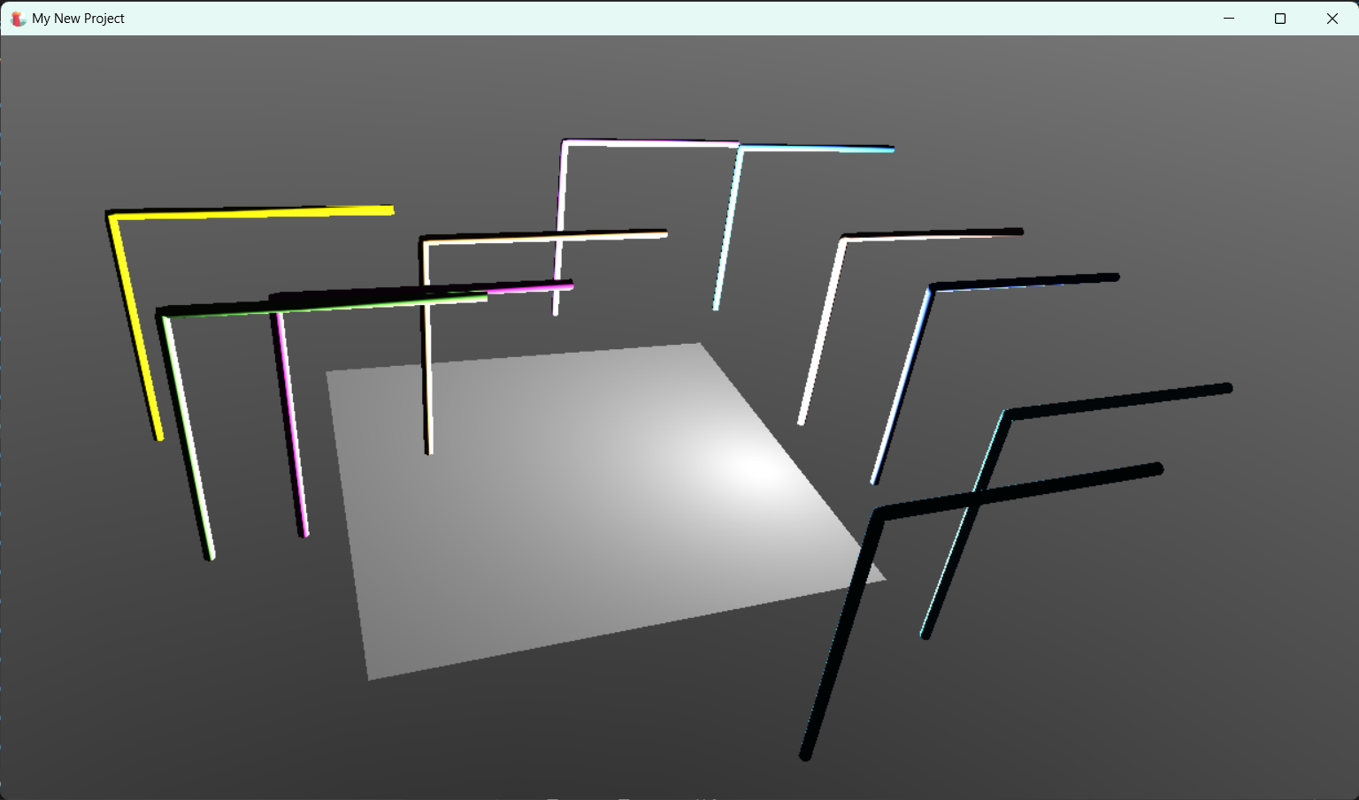 |
The following is an example code that uses TExtrusionNode to define a pipe. The pipe has a circular cross-section, and the spine is defined by a series of 3D points. The goal is to have a simple AddPipe routine that can be used like this to add more pipes to the viewport:
AddPipe([
  Vector3(0, 0, 0),
  Vector3(0, 2, 0),
  Vector3(0, 4.9, 0),
  Vector3(0, 5, 0),
  Vector3(0.1, 5, 0),
  Vector3(2, 5, 0),
  Vector3(5, 5, 0)
], 0.1);
See the AddPipe routine in the code below for details:
Complete code of a unit using an Extrusion.
To test it, create a new project from CGE editor using the "Empty" template, add "Viewport (3D)" on the design, then use this code for gameviewmain.pas.